
- Trane Manuals
- Air Conditioner
- Voyager YH Series
- Installation, operation and maintenance manual

Trane Voyager YH Series Installation, Operation And Maintenance Manual
- page of 64 Go / 64
Table of Contents
Troubleshooting, model number description.
- Model Number Notes
General Information
- Unit Description
- System Input Devices and Functions
- Unit Inspection
- Unit Clearances
Unit Dimensions
Unit weights, installation.
- General Unit Requirements
- Main Unit Power
- Space Temperature Averaging
Factory-Mounted Unit Options
- Circuit Breaker (FIYUCB) and Unit Disconnect (FIYUDC)
- Powered and Unpowered Convenience
- Return Air Smoke Detector
- Through the Base Gas Utility Option
- Air-Fi™ Wireless Communication Interface (WCI)
- Verifying Proper Air Flow (Units with Belt Drive Indoor Fan)
- Economizer Start-Up
- Compressor Start-Up
- Dehumidification Option
- Heating Start-Up
- Variable Air Volume Applications (Multi-Zone, Traditional VAV)
- Final System Set up
Sequence of Operation
- Reliatel Controls
- Two-Speed Indoor Fan (Title 24) Control
- Single Zone Variable Air Volume (Single Zone VAV) Control
- Variable Air Volume Applications (Traditional VAV)
- Constant Volume or Variable Air Volume Applications (SZVAV or Traditional)
Maintenance
- Fan Belt Adjustment-Belt Drive Units
- Monthly Maintenance
- Final Process
- Reliatel Control
- System Status Checkout Procedure
- Resetting Cooling and Heating Lockouts
- Zone Temperature Sensor (ZTS) Service Indicator
- Zone Temperature Sensor (ZTS) Test
- Programmable and Digital Zone Sensor Test
Wiring Diagrams
Advertisement
Quick Links
- 1 Model Number Description
- 2 Model Number Notes
- 3 Unit Description
- 4 Wiring Diagrams
- Download this manual
Related Manuals for Trane Voyager YH Series

Summary of Contents for Trane Voyager YH Series
- Page 1 Installation, Operation, and Maintenance Packaged Rooftop Air Conditioners Voyager™ – Cooling, Gas/Electric 12.5 to 25 Tons, 60/50Hz Model Number: YS*150–300 YH*150-300 SAFETY WARNING Only qualified personnel should install and service the equipment. The installation, starting up, and servicing of heating, ventilating, and air-conditioning equipment can be hazardous and requires specific knowledge and training. Improperly installed, adjusted or altered equipment by an unqualified person could result in death or serious injury.
- Page 2 (Global Harmonized System of Classification and compounds have the same potential impact to the Labeling of Chemicals) guidelines for information on environment. Trane advocates the responsible handling of allowable personal exposure levels, proper all refrigerants-including industry replacements for CFCs respiratory protection and handling instructions.
- Page 3 Copyright This document and the information in it are the property of Trane, and may not be used or reproduced in whole or in part without written permission. Trane reserves the right to revise this publication at any time, and to make changes to its content without obligation to notify any person of such revision or change.
Page 4: Table Of Contents
Page 5: model number description, page 6: model number notes, page 7: general information, page 8: system input devices and functions, page 9: sensors.
- Page 10 General Information The sensor is used to detect high temperatures due to fire Maintenance Instructions provided with the literature in the air conditioning or ventilation ducts. The sensor is package for this unit. designed to mount directly to the sheet metal duct. Each kit In order for the supply air smoke detector or return air contains two sensors.
Page 11: Unit Inspection
Page 12: unit dimensions.
- Page 13 Unit Dimensions Figure 2. Unit dimensional data for 12½ tons standard efficiency units DOWNFLOW CONDENSATE DRAIN CONN 1”(25MM) NPT 7/8”(22MM) DIA. HOLE (UNIT CONTROL WIRE) 1/2 NPT GAS CONNECTION 2”(51MM) DIA. HOLE (UNIT POWER WIRE) SERVICE GAUGE PORT ACCESS Note: ½ NPT Gas Connection Figure 3.
- Page 14 Unit Dimensions Figure 4. Horizontal duct dimensional data 12½ tons standard efficiency units CLEARANCE 48” CLEARANCE 60” 1219 MM 1524 MM FILTER ACCESS DOOR HORIZONTAL UNITS CLEARANCE 72” ONLY 1829 MM SUPPLY RETURN HORIZONTAL CONDENSATE DRAIN CONNECTION 1.0 IN. NPT CLEARANCE 38”...
- Page 15 Unit Dimensions Figure 6. Unit dimensional data 15–25 tons high efficiency units Note: ½ NPT Gas Connection Figure 7. Unit dimensional data 15–25 tons standard efficiency units, 12½–25 tons high efficiency units RT-SVX26R-EN...
- Page 16 Unit Dimensions Figure 8. Horizontal duct dimensional data 15–25 tons standard efficiency units, 12½–25 tons high efficiency units RT-SVX26R-EN...
Page 17: Unit Weights
Page 18: rigging, page 19: installation.
- Page 20 Installation Factory Installed Economizer trap condition which could result in condensate backup due to “air lock”. • Ensure the standard economizer has been pulled out Figure 11. Condensate trap installation into the operating position. Refer to the economizer Installation Instructions for proper setup. Note: Low Leak Economizers do not pull out.
Page 21: Main Unit Power
- Page 22 Installation Controls using 24 Vac Table 4. Zone sensor module wiring Distance from Unit to Before installing any connecting wiring, refer to “Unit Control Recommended Wire Size Dimensions,” p. 12 for the electrical access locations 0–150 feet (0–45.7 m) 22 gauge (0.33 mm provided on the unit and Table 3, p.
- Page 23 Installation Figure 15. ReliaTel relative humidity sensor (dehumidification option) Figure 16. ReliaTel humidistat (dehumidification option) RT-SVX26R-EN...
- Page 24 Installation Figure 17. Typical field wiring diagrams for optional controls (ReliaTel only) BAYSENS075* BAYSENS075* BAYSENS108* BAYSENS106* BAYSENS110* BAYSENS119* BAYSENS073* BAYSENS074* BAYSENS075* ASYSTAT669A OPTIONAL REMOTE SENSOR CONTROL BOX RTRM TEST 1 TEST 2 RT-SVX26R-EN...
Page 25: Space Temperature Averaging
- Page 26 Installation Table 6. Space temperature averaging examples RT-SVX26R-EN...
- Page 27 Installation Figure 19. Typical unit gas train configuration Table 7. Gas heater operating data Heating Input Rate—Btu/h 135,000 205,000 Minimum Supply Gas Pressure Natural/ 3.5” w.c./ 8.0” w.c. Manifold Gas Pressure -0.2” w.c Combustion Blower Suction Pressure (1 -2.1 to -3.1” -0.8 to -1.2”...
- Page 28 Installation Each reading must fall within the utilization range stamped on the unit nameplate. If any of the readings do not fall WARNING within the proper tolerances, notify the power company to Hazardous Voltage! correct this situation before operating the unit. Disconnect all electric power, including remote Excessive three phase voltage imbalance between phases disconnects before servicing.
- Page 29 Installation Modulating Gas Heat 2.5:1 Turndown during compressor starts. Oil foaming occurs when refrigerant condenses in the compressor and mixes with (Optional) the oil. In lower ambient conditions, refrigerant migration The set-up required for equipment ordered with to the compressor could increase. modulating gas heat varies based on the control system When the compressor starts, the sudden reduction in utilized.
Page 30: Factory-Mounted Unit Options
Page 31: powered and unpowered convenience, page 32: return air smoke detector.
- Page 33 Factory-Mounted Unit Options Figure 24. Return air smoke detector for downflow units THREE PIECE HOOD PLASTIC ELBOW METAL INTAKE TUBE SMOKE DETECTOR COPPER TUBE (FACTORY INSTALLED) VINYL TUBES (7-3/4 INCHES LONG) VINYL TUBES (2 INCHES LONG) METAL EXHAUST TUBE (16.34 INCHES LONG) TUBES INSTALL FROM BOTTOM, TOP DOES NOT NEED TO BE REMOVED FROM SMOKE DETECTOR...
- Page 34 Factory-Mounted Unit Options unit must be between 500 and 4000 feet per minute. Most Figure 25. Smoke detector wiring scheme models of equipment covered by this instruction will develop an airflow velocity that falls within these limits over the entire airflow range specified in the evaporator fan performance tables.
Page 35: Through The Base Gas Utility Option
Page 36: air-fi™ wireless communication interface (wci), page 37: pre start, page 38: start up, page 39: dehumidification option.
- Page 40 Start Up pressure of 0.3" w.c. to 2.5" w.c. respectively with a Table 15. Variable air volume mode operation deadband adjustment range from 0.2" w.c. to 1.0" w.c. The System Mode Fan “Auto” Fan “On” setpoint is adjustable on the RTAM Static Pressure DWU or Setpoint potentiometer or through ICS.
Page 41: Final System Set Up
Page 42: sequence of operation.
- Page 43 Sequence of Operation actuator (ECA) to open the economizer damper. The RTRM The potentiometer located on the ECA is non-functional tries to cool the zone utilizing the economizer to slightly when both the temperature and humidity sensors are below the zone temperature setpoint. If the mixed air installed.
Page 44: Two-Speed Indoor Fan (Title 24) Control
- Page 45 Sequence of Operation Demand Controlled Ventilation Operation and remains there for a few minutes, the unit will begin to stage up compressors. If the supply fan is on when the first Demand Controlled Ventilation for units with 2-Speed stage compressor is energized, it will remain energized or Supply Fans will require an additional module (RTVM) for energize at low speed for the duration of Cool 1.
Page 46: Single Zone Variable Air Volume (Single Zone Vav) Control
- Page 47 Sequence of Operation By default, the Design Minimum Position schedule will be point that would make the Design Minimum Position a linear line through all user selectable Design Minimum schedule linear. Position setpoints. The user will have the ability to set the Provisions have been made in Service Test Mode to allow Design Minimum Position at Middle fan speed command for proper damper minimum position setup:...
Page 48: Variable Air Volume Applications (Traditional Vav)
- Page 49 Sequence of Operation If the unit has modulating heat, the unit can be made to do ranges are from 50°F to 90°F. When the zone temperature discharge heating with VAV control. This is done by meets or exceeds the MWU setpoint, the unit will switch to placing a contact closure across the “Changeover Input”...
Page 50: Constant Volume Or Variable Air Volume Applications (Szvav Or Traditional)
- Page 51 Sequence of Operation mounted in the indoor section and is connected to the (a) Exhaust mode 3 is not available with the tracking power exhaust option. RTOM. The clogged filter switch is normally open and will (b) For units configured with the Statitrac option, the Exhaust Damper automatically close when the pressure differential across will open during Ventilation Override modes that request the ex- the filters falls below the clogged filter setpoint.
- Page 52 Sequence of Operation Lead/Lag input. When it is activated, each time the designated lead compressor(s) is shut off due to the load being satisfied, the lead compressor or refrigeration circuit switches. When the RTRM is powered up, i.e. after a power failure, the control will default to the number one compressor.
Page 53: Maintenance
Page 54: monthly maintenance, page 55: final process, page 56: troubleshooting, page 57: resetting cooling and heating lockouts, page 58: zone temperature sensor (zts) service indicator, page 59: programmable and digital zone sensor test.
- Page 60 Troubleshooting WARNING Hazardous Voltage! Disconnect all electric power, including remote disconnects before servicing. Follow proper lockout/ tagout procedures to ensure the power can not be inadvertently energized. Failure to disconnect power before servicing could result in death or serious injury. 1.
Page 61: Wiring Diagrams
Page 62: warranty.
- Page 63 Warranty residential application. Commercial use is any application where the end purchaser uses the product for other than personal, family or household purposes. *A 5 year limited warranty is provided for the optional Low Leak Economizer, when combined with the optional FDD (Fault Detection and Diagnostics) option.
- Page 64 For more information, please visit trane.com or americanstandardair.com. Trane and American Standard have a policy of continuous product and product data improvement and reserve the right to change design and specifications without notice. We are committed to using environmentally conscious print practices.

This manual is also suitable for:
Rename the bookmark, delete bookmark, delete from my manuals, upload manual.
ComfortSite Login
Trane ComfortSite is an extranet site designed to save you time. With your secure login, you can:
- Order Equipment, Parts, Literature and track Order Status
- View product literature
- Register for Training programs
- Complete Warranty requirements online
- Search for specific Product Information
- Use interactive Product Support functions
- View and print invoices through Account Track Online
Trane Connect
This is the login for Trane® Connect™ and other Trane® commercial applications. Trane® Connect™ is our secure, cloud-based customer portal to access your building systems to remotely monitor and manage building systems, and conduct routine maintenance.
- Looking for Parts?
- Safety Data Sheets
- Customer Login
CONTACT A TRANE EXPERT
Symbio® 700 controller.
- Select Play
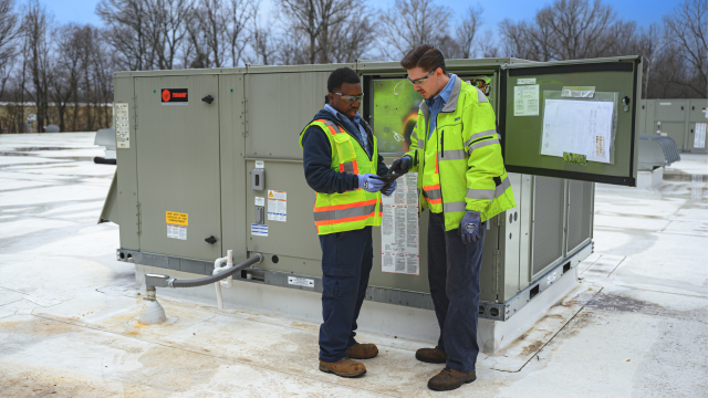
The Symbio 700 Controller is Trane's digitally enabled equipment controller for rooftop units and split systems, including Odyssey™, Precedent®, Voyager® 3, Axiom® Rooftop Water Source Heat Pumps. This line of equipment controllers enables innovative and scalable building automation through advanced HVAC equipment control, analysis, monitoring, operation, and servicing
- Easy installation, start-up and commissioning through the Symbio Service and Installation App - no special tools required.
- The onboard display clearly describes system alarms and resolutions, no flash codes.
- Service and troubleshoot equipment from your mobile device.
- Remotely monitor alarms, trends, and event logs.
- Communications via open standard protocols (BACnet, Modbus, Lontalk), through wired, wireless, and IP.
Contact Us to Learn More
Why symbio 700.
HVAC systems use about 35% of a building’s energy on average according to the U.S. Department of Energy. Symbio 700 controllers, with Trane’s professional, adaptable performance programming, help to maximize equipment energy efficiency. It’s all part of Trane’s mission to bring more buildings up to speed with today’s higher sustainability standards.
Flexibility
Easy integration with existing systems and upgradable software for proactive cybersecurity, ongoing enhancements and building optimization.
Connectivity
Optimize productivity by giving customers access to remotely monitor & control the equipment so you can troubleshoot more efficiently.
Serviceability
The mobile app makes servicing the unit easier than ever. Complete setpoint changes and a range of troubleshooting tasks from your device.
Download the Symbio Service and Installation App
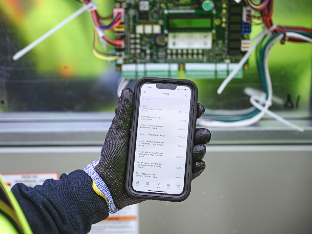
Designed for field technician and contractor use, Trane’s Symbio Service and Installation App makes setup and servicing easier than ever. The app provides guidance via smartphone for ease of installation and startup that works anywhere using Bluetooth. It enables contractors to complete setpoint changes and a range of service and troubleshooting tasks, and provides owners the option to gain remote access to the equipment and its data through a secure portal.

Bluetooth Connectivity
The Trane Symbio 700 equipment controller pairs with the Symbio mobile application using Bluetooth Low Energy (BLE). By pairing with the Symbio 700 controller, technicians can use the Symbio mobile application to edit operating setpoints, adjust other parameters and settings, and perform a range of service and troubleshooting tasks while standing at the unit.
Onboard Display
In addition to the Symbio Service and Installation App, the unit can also be configured via the onboard user interface. The Symbio onboard display is an embedded Backlit LCD display complete with navigational buttons. The interface allows the user to view status, configure, and troubleshoot the unit without additional tools. The embedded menu structure is complete with alarms, status, service, settings, and utilities that use real language - no flash codes to interpret.
Looking for Symbio 700 Firmware Downloads?
Download the Symbio 700 Controller Firmware for Packaged Units & Split Systems
Contractor Support Center
Customer goals evolve. Technologies change. In our world, there’s always something new. Trane strives to provide contractors all they need in order to be successful on the job. Use these resources below to stay in the know and on top of your game.

Symbio 700 On-Demand Training
Trane offers a wealth of educational opportunities and resources for engineers, designers, contractors, technicians, engineering students and professors. This course covers new product information with an emphasis on Symbio 700 controllers used with new Precedent units.

Light Commercial Help Center
Trane is dedicated to helping contractors be more effective at installing and servicing Trane light commercial control systems for small and medium-sized buildings. Access technical support and a range of resources for any Trane light commercial products.
Symbio 700 Service and Installation App How-To Videos
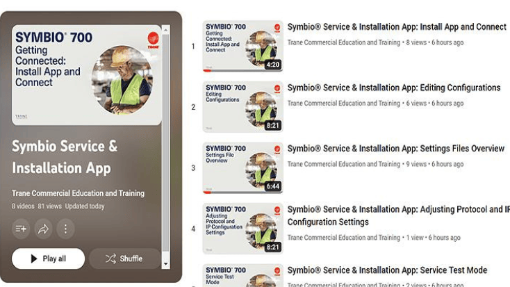
Symbio® 700 Controller and Service & Installation App How-To Videos are now available on YouTube. Symbio 700 unit controllers now ship standard on many systems going forward - stay up to date on best installation and service practices.
Product Literature
- Symbio® Equipment Controls BAS-SLB140*-EN Download
Product Data Sheets
- Symbio® 700 PICS BAS-PRG024*-EN 172KB Download
Installation Instructions
- Symbio Service and Installation App Quick Start Guide BAS-SVN043*-EN Download
- Symbio 700 Controller User Guide BAS-SVU054*-EN Download
Let's Get Connected
Explore more solutions from Trane to connect your entire building and optimally operate all systems.
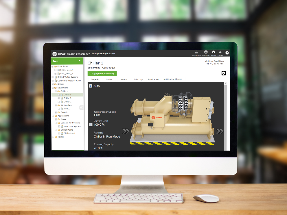
Sustainability hinges on building automation
Trane provides end-to-end connectivity solutions and strategies for buildings of every size, function and age.
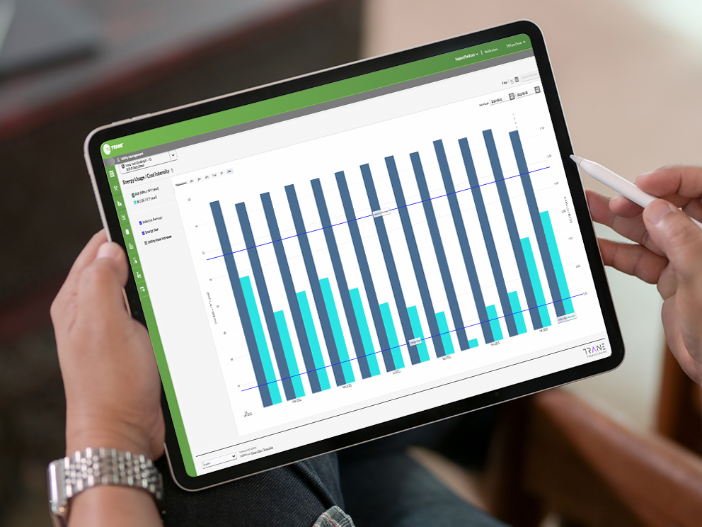
Proactively maintain and optimize your HVAC system
Symbio enables remote monitoring and performance reporting that help maintain uptime at its highest performance level.
Memorial Museum V.I. Lenin

Most Recent: Reviews ordered by most recent publish date in descending order.
Detailed Reviews: Reviews ordered by recency and descriptiveness of user-identified themes such as wait time, length of visit, general tips, and location information.

Also popular with travelers

Memorial Museum V.I. Lenin, Ulyanovsk

IMAGES
VIDEO
COMMENTS
For All Your Commercial HVAC Education & Training Needs. Trane offers a wealth of educational opportunities and resources for engineers, designers, contractors, technicians, engineering students and professors. We offer on-site classroom training as well as interactive courses suited to a wide range of skills and expertise, from maintenance ...
Voyager 3 units are capable of integrating into building automation and control systems for optimization, monitoring and data analysis. New models are equipped with the Symbio® 700 controller for improved usability and automated optimization. Symbio's intuitive user interface displays system alarms, diagnostics and resolutions.
An effective way to learn. Trane University integrates innovative teaching technologies for instructor-led, distance learning and online courses and webinars. Interactive and hands-on experience uses proprietary Trane-developed tools for load, system, energy and economic analysis. Extensive knowledge base. Experienced professional trainers have ...
operation, and maintenance procedures for Voyager 3 units. By carefully reviewing the information within this manual and following theinstructions, risk of improper ... Factory training is available through Trane University™ to help you learn more about the operation and maintenance of your equipment. To learn about available training
operation, and maintenance procedures for Voyager 3 units. By carefully reviewing the information within this manual and following the instructions, the risk of improper ... Factory training is available through Trane University™ to help you learn more about the operation and maintenance of your equipment. To learn about available training
To register for training, each learner must create an individual account in Trane Education Center. View our FAQ section for step-by-step instructions. Note: Trane reserves the right to reject any training course enrollment. Payment Payment options: • Major credit card (preferred method) • Purchase order (PO number must be provided when
Summary of Contents for Trane Voyager YH Series. Page 1 Installation, Operation, and Maintenance Packaged Rooftop Air Conditioners Voyager™ - Cooling, Gas/Electric 12.5 to 25 Tons, 60/50Hz Model Number: YS*150-300 YH*150-300 SAFETY WARNING Only qualified personnel should install and service the equipment. The installation, starting up ...
In the unlikely event that a problem does occur, the Micro's on-board diagnostics are there to assist and get you back on line fast. Trane is a pioneer in the HVAC industry and has extensive experience in the design of hardware and software. This manual provides the information necessary to proficiently troubleshoot the Voyager 3-25 ton UCP ...
Trane Heating & Air Conditioning
Trane products. Upon course completion, students will have been exposed in detail to the mechanical, electrical and control systems of these units and will have become knowledgeable in the start-up, maintenance and troubleshooting requirements of these products. OCTOBER 4-5, 2022 8 am - 5 pm each day Application and Options • Precedent & Voyager
Troubleshooting diagnostic and resolution of trane voyager RTU | roof top unit. Hvac no cool service call problem solved. Trane voyager training.#d2dnyac #h...
The Voyager III IOM, RT-SVX34M-EN has instructions (pgs. 50-55) on how to set the Outside Damper position or Outside Airflow setpoint for Constant Volume (CV), Multi-zone VAV (MZVAV) and/or SZVAV units with or without the Demand Control Ventilation option. The problem that most techs run into 99% of the time is that the Outside Damper position ...
Reliatel Testing
Trane is a pioneer in the HVAC industry and has extensive experience in the design of hardware and software. This manual provides the information necessary to proficiently troubleshoot the Voyager 3-25 ton UCP controlled models. This publication covers UCP controls only. This publication does not cover all aspects of service.
• Voyager units incorporate the Trane-Tite-Top (T3 ). Each part of the top (three pieces) overlaps in such a way that water cannot leak into the unit. These overlapped edges are gasketed and sealed to ensure superior water integrity. • Quick- Access panels reduce the number of possible water entry points. • For added water integrity ...
Voyager™ 12½-25 Ton Packaged Rooftop Units ... High Efficiency Motors Trane® Communication Interface (TCI)(h) (h)TCI is for use with non-VariTrac™ systems and VariTrac systems. High Short Circuit Current Rated (SCCR) Electrical Subsystem(i) (i) Available on 208 V/60 Hz, 230 V/60 Hz, and 480 V/60 Hz only.
When the combustion fan is running, and before the gas valve opens, the pressure reading on the outlet side of the gas valve will be in the range of -2.5" to -3.5" w.c. When the gas valve opens during normal ignition, the pressure will increase upwards to -0.2" w.c. The maximum allowable pressure for proper ignition is -0.05" w.c.
The Symbio 700 Controller is Trane's digitally enabled equipment controller for rooftop units and split systems, including Odyssey™, Precedent®, Voyager® 3, Axiom® Rooftop Water Source Heat Pumps. This line of equipment controllers enables innovative and scalable building automation through advanced HVAC equipment control, analysis ...
Updated. TCI-R Reliatel Voyager replacing TCI-3 UCP Voyager. Summary: By following these steps, you should be able to successfully replace your TCI-3 UCP Voyager with the TCI-R Reliatel Voyager. Remember to exercise caution, adhere to safety guidelines and seek professional assistance if necessary. WARNING:
Flag of Ulyanovsk Coat of Arms of Ulyanovsk. Ulyanovsk (Russian: Улья́новск), formerly Simbirsk (Russian: Симби́рск), is a city on the Volga River in Russia.It was founded in the year 1648. Ulyanovsk had a population of 638,300 in 2005. It is the administrative center of Ulyanovsk Oblast.In 1924, the city was renamed Ulyanovsk after Vladimir Ulyanov, better known as Lenin ...
There is a school which Lenin studied. This museum was built to celebrate 100 years of Lenin's birth. Two houses which Lenin was born and grew up moved into this site from their original place in Ulyanovsk at that time. This beautiful area is located on the hill near Volga river. Surname of Lenin is Ulyanov.
Website. aviastar-sp.ru at the Wayback Machine (archived 2022-04-15) CJSC Aviastar- SP ( Russian: «Авиастар-СП») is a Russian aircraft factory based in Ulyanovsk and founded in 1976. It is a closed shares joint stock company. It replaced the Soviet Ulyanovsk Aviation Industrial Complex and manufactures the cargo aircraft An-124 ...
The Legislative Assembly of Ulyanovsk Oblast ( Russian: Законодательное собрание Ульяновской области, romanized : Zakonodatel'noye sobraniye Ul'yanovskoy oblasti) [4] is the regional parliament of Ulyanovsk Oblast, a federal subject of Russia. A total of 36 deputies are elected for five-year terms.