
OR WAIT null SECS
- Do Not Sell My Personal Information
- Privacy Policy

© 2024 MJH Life Sciences ™ and Turbomachinery Magazine . All rights reserved.

Turbine overspeed testing
Turbine overspeed events lead to costly and dangerous catastrophic failures. Therefore the overspeed system has to be periodically tested to ensure the system has the adequate response time to protect the turbines, plants and personnel.
Below are excerpts from the paper, "Turbine overspeed systems and required response times" by Scott L Taylor of Woodward and Sheldon S Smith of American Electric Power at the 2009 Turbomachinery Symposium in Houston.
Regular, periodic testing is the only way to ensure a protection system is working. In some cases, without exercising the system, mechanical components may become stuck rendering the protection system inoperable. Regular testing of stop or trip valves is generally recommended on a weekly or monthly basis where possible. Additionally it is recommended to shut down with the trip valve(s) whenever possible.
One of the largest owner/operators of power generation equipment requires annual testing on large machines. For mechanical bolts a minimum of two tests are required. If the trip speed of the second test is higher than the first, then a third test is required. Electronic systems can be tested at lower speed. Where there are exceptions to this rule the specific test requirements would have to be recommended by the turbine OEM.
Another very large owner/operator allows low speed trips for testing but requires a “full stress” (full speed) test after any front standard work that could affect speed sensors, wiring, and gap.
Specific test recommendations will come from OEMs and insurance carriers and each owner/operator will establish test requirements for a specific unit. There are a number of studies that discuss testing frequency based on recorded failure probability either across the industry or for a given site. These procedures should not be considered static. As more experience is gained with the unit or as the unit is modified, these procedures, test scope, and test intervals, should be reexamined. Also, as root causes of incidents of all units are examined and shared, new best practices may be recognized.
Low Speed T esting
On generator applications, the full overspeed test point exerts tremendous forces on the rotating components of the turbine and generator. This can lead to increased maintenance costs in the long run so there is some incentive to perform the overspeed system test at a lower rpm.
On compressor or pump applications, it is often (but not always) physically impossible to achieve the overspeed setpoint with the compressors or pumps connected. So users perform overspeed tests with the units uncoupled. Uncoupling and recoupling is a labor intensive process. When uncoupled, the rotational inertia of the system is greatly reduced. This means the control dynamics for the normal system and the uncoupled system are different. This may require entering a different set of dynamics or retuning the governor system for testing (and making sure the original governing system dynamics are restored when the test is complete). In some cases special functions have been added to the governing system to support additional modes for uncoupled testing. Again, there is a risk that the modes of operation be specified or selected correctly.
In both of the above cases there are compelling reasons to perform at least some of the tests of the overspeed protection system at a lower speed. But, insurance carriers and corporate testing requirements must also be met. Some sites require validation of the trip system functionality at full speed but then allow lower speed tests provided no changes are made in the system, particularly with the speed pickup, brackets, or sensing gear that could affect the ability to properly sense speed. There are some specific case examples that demonstrate the value of full speed testing.
T rip System T esting While Running
Many units run for long periods of time, multiple years, between outages. So there may be extended periods of time where actual trip testing cannot be performed. To ensure reliability and availability of the overspeed protection system, periodic partial system testing is performed. This may include confirming mechanical/hydraulic operation of a part of the trip system or performing some simulated test on part of the electronic system while the trip circuit is partially blocked. Ideally the systems should be designed with enough redundancy that protection is not compromised during the test process (but this is not always the case).
In some systems it is possible to do some level of valve testing either at rated or reduced load conditions. While this is valuable, and in some cases necessary to ensure the operation of the valve, it does not guarantee a proper seating of the valve. So there is still a case for a full functional trip test (although this need not be from full trip speed).
Risks of T esting
An overspeed event requires three components:
- Loss of load,
- Failure of the control, and
- Failure of the overspeed protections system.
During an overspeed test the unit is not loaded and the control may be partially compromised by operating above normal operational speeds and, where driving equipment is uncoupled, with a significantly reduced inertia. The overspeed test requires putting the protection system into an abnormal state—either by changing setpoints, overriding normal governor limits, and possibly operating with a different set of system dynamics. So the last line of defense may be the very protection system that is being tested to confirm its functionality. A significant number of overspeed incidents, by some estimates nearly half, occur during testing. Obviously some preliminary testing is required prior to performing a full overspeed test. This may include performing a low speed test prior to full speed testing.
After a successful test is performed it is equally important that the system be restored to the normal operating state. A second set of tests, such as simulated speed testing if the setpoint was changed, should be performed to confirm the system is correctly restored to its normal operating conditions.
INCIDENTS AND ROOT CAUSE ANALYSIS
In one case a boiler feedpump turbine (BFPT) was tested at less than full overspeed trip for years. The setpoint was dialed down for the test and then reset. A safety audit required a full speed test. At 8000 rpm the unit did not trip and an emergency trip was selected. Next year the trip failed again. The third year the controls group got involved. The trip system electronics and program appeared to be correct. When the turbine was tested, above 6200 rpm the overspeed device started to miss pulses and the sensed speed dropped but not enough to trigger loss of speed sensed logic. Work was done by the OEM on the front standard and on the sensing wheel and the unit worked. Although the exact cause of the problem was not identified, one thought is that the rotor shifted slightly at high speeds and that only in those conditions would the speed signal be partially lost. Tests with a frequency generator to simulate speed would not have exposed this problem.
In another case a BFPT was tripped for no apparent reason. Just prior to this, another BFPT had tripped and the distributed control systems (DCS) increased the demand to the second BFPT. It picked up speed and tripped. It was not immediately obvious that an overspeed had occurred. On analysis of the data it was recognized that it tripped at the mechanical overspeed trip setpoint. The electronic governor setpoint was scaled as 0 to 10,000 rpm when the operating range was only around 8000 rpm. The controllers protected overspeed were set to 105 percent of this total range (not 105 percent of the normal maximum operating point). On this unit additional instrumentation was added to annunciate the overspeed bolt trip and the controller was rescaled to the proper operating range.
It is critical that the industry look to and share incidents and root cause analysis to determine how to prevent the repetition of mistakes.
RESPONSE TIME TESTING
API 612 (2005) 16.3.4.6 states, “The response time of the overspeed shutdown system shall be recorded to confirm compliance with the requirements of 12.3.1.1.” But this is in a list of optional tests that may be performed as shop tests and not a regular test requirement.
A great deal of emphasis is placed on overspeed testing but this is done under controlled conditions. Speed is raised slowly to the trip point. This confirms the overspeed trip setpoint but does nothing to confirm the dynamic response of the trip system. This factor is as critical as the setpoint.
The authors have shown that the response time of the entire trip system is critical to the protection of the turbine and that relatively small variations (undetectable to an operator) are very significant. Since the timing of these electrohydraulic circuits is so important and the systems so complex, the need to periodically record the trip time and then trend those response times to identify any progressive degradation in the system seems obvious. In the past, achieving a resolution of 1mS to evaluate the response time of a trip system would require specialized equipment but today this is readily available from sequence of event (SOE) cards in DCS systems and programmable logic controller (PLC) systems.
Periodic trip system response time testing, as with the overspeed setpoint testing, is needed to ensure the overspeed prevention system is operating as designed and that the required level of equipment and personnel protection is provided.
Related Content:

- Search Search
- Protection systems
- Monitoring systems / software
- Sensors & transmitters
- Engineering solutions
- Troubleshooting
- Turnaround service
- Machine safety consultancy
- Rotating equipment
- Wind turbines
- Speed protection systems
- Speed monitoring systems
- Speed sensors
- Manufacturer (OEM) solutions
- Book Vibration
- E-book: Wind Turbine Optimization
- Vibration Training (CAT1+)
- Speed sensors: Hall-effect
- Speed sensors: Eddy current
- Speed sensors: Variable reluctance
- About Istec
Mechanical overspeed protection or electronic overspeed protection?
10 April 2020 Theme: Machine protection

In the past, overspeed turbine protection systems were often designed by the turbine OEMs themselves as part of the mechanical system. These mechanical protection systems are still in use, especially on medium-sized machines. However, electronic systems offer significant benefits and are becoming increasingly accessible, in both their economical and technical impact. This article explains the benefits of electronic protection over mechanical protection.
The principle of mechanical overspeed protection
To understand the difference between the two types of protection, it is important to understand how mechanical overspeed protection works. Mechanical overspeed protection systems use a weight on a spring of which the spring force is known. Due to the centrifugal force as a result of the shaft rotation speed, the spring is stretched further and further and the weight moves out. As long as the rotational speed is still within the design specifications, the spring will not stretch too far and the weight will not protrude. However, if it exceeds its design specifications, the weight will run out and hit the trip bolt. This will release the pin and the trip will be activated.
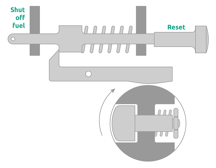
The operation of a mechanical overspeed monitoring system.
The principle of electronic overspeed protection
Electronic overspeed protection consists of a gear or other measuring surface, speed sensors and a measuring system with trip logic and relay outputs. The speed sensors look at the measuring surface and give a sine or square wave signal, which the measuring system sees as pulses. The measuring system then counts the time between pulses to determine the rotation speed. The relay outputs are controlled by trip logic. In order to increase safety and availability, these protection systems are often built with redundant voting structures.
Why switch to electronic overspeed protection?
Switching from mechanical overspeed protection to electronic overspeed protection has significant advantages. Verifiable security is the primary argument. To illustrate: where mechanical overspeed protection systems have to be tested by actually overspeeding the machine (with all the risks involved!), an electronic overspeed protection system can be tested by simulating overspeed. In addition, a simulated test is quicker and easier to perform.
In this overview we compare both forms of machine overspeed protection:
Switching to electronic overspeed protection is not complex. Firstly, the mechanical trip lever and all associated system components are removed. Secondly, a measuring surface (gear) is mounted on the shaft if this is not already available, after which one or more sensors are placed around this measuring surface. The monitoring system can then be placed near the machine or in a cabinet.
Learn more about overspeed:
What does the API Standard 670 state about overspeed detection systems? »
SpeedSys 300 – Overspeed Protection System
The SpeedSys 300 is a SIL 3 rated electronic overspeed protection system for rotating machinery. It delivers the core layer of protection with a compact architecture. Its small technical footprint enables low-impact retrofitting and extends the range of machinery which can be protected.
Learn more about SpeedSys 300 »
What does the API Standard 670 state about overspeed detection systems?
5 speed-related failures with rotating machinery, sensors for speed measurements, learn more:.
12 July 2022 Theme: Machine protection
The API Standard 670 is an industry standard and describes the minimum requirements for a machine protection system (MPS). This includes, measuring radial shaft vibration, casing vibration, axial shaft position,…
22 November 2019 Theme: Machine protection
Rotating machinery such as turbines, pumps and compressors are continuously subjected to major mechanical forces. As most of these machines are critical to the process, systems are implemented with protection…
10 October 2019 Theme: Machine protection
Choosing the right speed sensor for an application is of crucial importance for an accurate and reliable measurement. After all, the signal of the sensor is the input for an…
Istec International © 2024. Alle rechten voorbehouden
Istec International uses cookies. By clicking 'Accept cookies' or by using this website you confirm agreeing to this. Learn more about the used cookie.
- Emerson.com
- About the Blog
Electronic Turbine Overspeed Protection
by Jim Cahill | Aug 1, 2018 | Asset Management , Control & Safety Systems | 0 comments
At the 2018 Ovation Users’ Group Conference, Emerson’s Sam Onuska and Greg Lieb presented improvements in advanced overspeed protection and online, real time testing of overspeed systems.
Greg opened describing where overspeed protection systems can be applied including steam turbines, gas turbines, boiler feed pump turbines (BFPTs) and hydro turbines. These systems measure the shaft rotational speed and decide & take action based on overspeed conditions by providing a method to reduce rotational velocity.
Here’s a view of a typical mechanical overspeed system:

During an upgrade the trip lever and all associated linkages, hydraulic trip valve, pressure switches and tubing associated with the mechanical overspeed trip, reset and test are removed. Typically, the rotor-mounted equipment remains due to rotor balance considerations and costs versus benefits of removal.
Components of an Electronic Turbine Overspeed Protection system include speed probes—Eddy current, Hall-Effect, or variable reluctance probes. The decision and action steps are automated within the electrical overspeed protection system. In the decision step, a pulse train or sine wave is converted to rotational speed and compared with a speed setpoint. In the action step, if the setpoint is exceeded a relay’s state is changes and voted or non-voted outputs sent to initiate a trip.
An independent overspeed controller has redundant power supplies, 3 dedicated overspeed sensing channels, 3 digital output I/O for all other Ovation trips and testable dump manifold (TDM) testing.

Modes of testing include offline card overspeed testing, online card overspeed testing, testable dump manifold trip, and turbine manual trip.
General guidelines for electronic overspeed protection systems are detection prior to 110-112% rated speed with the setpoints specific to the turbine make and model. Per the API 670-Machinery Protection Systems standard, overspeed reaction time should less than 40msec. The response to the observed overspeed condition should limit the speed to less than 120% of the rated speed. This response is influenced by the module configuration, sampling rate and rotor acceleration.
The total system response consists of overspeed detection, trip signal to hydraulic system and hydraulic actuator / valve closure.
The advantages of electronic systems vs. mechanical systems include no moving parts, common set of spares, no loss of production during testing, turbine not placed in unsafe conditions, tunability of the system, improved live data and historical view and fault tolerance.

Share this:
Subscribe to podcast, related posts.
We invite you to follow us on Facebook, LinkedIn, Twitter and YouTube to stay up to date on the latest news, events and innovations that will help you face and solve your toughest challenges.
Do you want to reuse or translate content?
Just post a link to the entry and send us a quick note so we can share your work. Thank you very much.
Our Global Community
Emerson Exchange 365
The opinions expressed here are the personal opinions of the authors. Content published here is not read or approved by Emerson before it is posted and does not necessarily represent the views and opinions of Emerson.
Privacy Policy | Cookie Policy | Data Protection Statement

Our combined knowledge, your competitive advantage
Wind turbine refurbishment key to achieving decarbonised power system by 2035
- Share on Linkedin
- Share on Facebook

Wind power is big business, and is under pressure to reduce costs and carbon footprint. This can be done by proactively looking after the most valuable turbine components, with solutions that seek to repair and extend the lifespan of these parts and avoid long-distance, carbon-intensive and expensive transport.
On one day in November 2022, more than 20.896GW (70%) of the UK’s electricity was produced by wind, and that record was broken shortly after on December 30 when 20.918GW (87.2%) was generated by UK based wind turbines. Britain produced a record amount of wind power in 2022, the National Grid revealed on 6 January.
Wind produces on average over 25% of the United Kingdom’s energy needs annually and there are now more than 11,000 wind turbines onshore and offshore with an installed capacity of over 25 gigawatts. And this capacity is set to boom further, driven by energy security concerns and the cost of natural gas.
The UK Energy Security Strategy 2022 has set a goal of 95% low carbon power by 2030. To meet the 6th Carbon Budget, we will need a fully decarbonised power system by 2035. To achieve this the Government intends to quadruple offshore wind capacity to 50GW and the renewable energy industry also believes onshore wind capacity needs to increase to 30GW by 2030.
This rapid expansion of wind energy in the UK means more wind turbine manufacture, installation, operation, repair, refurbishment and replacement. A growing number of MPs have come out in favour of a reversal of the restrictions on new onshore wind farms, and according to the Offshore Wind Industry Council approximately £155bn of private sector investment is expected in offshore wind by 2030.
The expected life span of a commercial wind turbine is 20-25 years (source: Wind Europe) and the unit will need continual repair and maintenance during that period. The “workhorse” component in a wind turbine is the generator. During a turbine’s lifespan, the generator will require repair and maintenance and will quite often be replaced as it deteriorates due to age. Costs, logistics, lead times, manufacture and repair capacity, workforce and skills are all factors in achieving this replacement quickly and efficiently.
With a large proportion of existing turbines reaching the end of their OEM warranty periods, evidence from industry research points to the economic advantages of generator refurbishment, as the manufacturing and transportation of a full replacement has very high environmental as well as financial costs. Plus, the recyclability of wind turbines is under close scrutiny today – with the covid pandemic over, the Russia-Ukraine War in a period of stasis, and COP27 taking place, climate change is again top of the news agenda. ETIP Wind calculates that wind turbines are 85%-90% recyclable on average, with components like the gearbox, generator, foundation structure and tower all recyclable. Manufacturer Vestas cites that 83% of a turbine’s carbon footprint comes from the production of materials, while just 17% comes from transport.
Research by organisations including manufacturers and the UK’s Offshore Renewable Energy (ORE) Catapult say that electromechanical refurbishment is important to minimise wind’s own carbon footprint. Vestas states that a refurbished component can reuse up to 70% of the materials compared to a new product, and a refurbished component saves, on average, 45% of CO2 emissions compared to a new part, when reverse logistics – the cost of bringing the item from the turbine to the factory for repairs – is accounted for.
More stakeholders are pressing the case for a circular economy in renewable energy, especially wind power. The ORE Catapult, a private-public innovation centre, estimates that by 2050 the global wind industry will need to decommission as much as 85GW of offshore wind capacity and 1,200GW of onshore wind capacity. This provides an idea of the scale of the circular economy opportunity.
“Refurbishing of wind turbine generators has enormous, and largely untapped, potential,” says Chris Robson, Sales Director at Houghton International, an electromechanical engineering company.
“If the UK is to be “clean energy sourced” by 2035, we’ll need to construct thousands of new wind turbines while keeping the current capacity running. Many turbines are already exceeding their intended service life – so long as they’re maintained correctly. Rewinding and refurbishing a generator can extend its life by 20-years, and this will relieve some pressure on the new build programme.”
Grannell Community Energy Ltd – turning point
Houghton International is a service and repair company of electromechanical machines – generators, motors, transformers and pumps. Throughout its 38-year life, Houghton International (HI) has maintained, repaired and refurbished a very wide spectrum of these electromechanical assets but, while it had worked on ad hoc wind turbine generator maintenance, through the 2000s and 2010s the wind industry has been broadly reliant on OEM replacement or refurbishment.
In early 2020 Grannell Community Energy (GCE), a locally-funded Community Benefit Society, contacted Second Wind Energy LTD with a problem. The group had bought and installed a second-hand 480V / 800KW Enercon wind turbine, but the generator had failed after just one year in service. Second Wind Energy specialises in sourcing new and used turbines for customers, installing them and providing maintenance, and it also removes generators and turbine assets for repair.
GCE’s commercial scale wind turbine has a 4.2m diameter, 26-tonne generator located on a steel 50m tower. HI was the only UK based company that Second Wind Energy were satisfied could handle the full refurbishment of the damaged generator, and they responded quickly and positively, offering a competitively priced full rewind of the unit. The majority of wind generators operate through a gearbox so the much larger, direct drive generator was far less familiar to the team within HI, but their vast, multi-sector generator experience has given rise to a flexible, problem-solving approach. GCE’s generator was transported to HI’s Newcastle-upon-Tyne base, one of the only facilities in the UK that could accommodate such a big rotating machine. The project that unfolded proved to the customer, the wind turbine industry and HI there is a truly environmentally-conscious, effective solution for rewinding and extending the life of wind turbine generators here in the UK.
After assessing the damage, HI recommended a full rewind of the stator and rotor. Over 50 miles of copper wire, uprated to help ensure a long lifespan, was used in the rewind of the generator. The existing copper was stripped out and recycled. All 60 rotor bricks were reverse engineered and rewound using a process developed by HI that had been proven for decades on high-speed train alternators. The rotor bricks were put through a vacuum pressure impregnation process to seal them in a strong resin that is highly weather resistant and strengthens the entire rotor. The customer was delighted, and more wind turbine repair and life extension projects began to flow in.
The project demonstrated that Houghton International had the skills and knowhow to fully refurbish wind turbine generators, saving operators hundreds of thousands of pounds and many tonnes of carbon. “It’s not just the cost of repair or replacement to consider,” explains Robson.
“When a turbine is offline, that’s lost revenue or energy that must be sourced from elsewhere, potentially from non-renewable sources. Every day of downtime has both financial and environmental cost.”
For failed generators, the alternative is refurbishment or replacement by the OEM. Most offshore wind farms are in the North Sea, and the majority of the UK’s onshore wind farms are in Scotland – not so far from Newcastle-upon-Tyne.
“We believe that damaged and failed turbine generators – if they are selected for repair – are often shipped from the North Sea to the country of origin, to the OEM, in which could be anywhere from Germany or Denmark to somewhere in Asia,” says Chris Robson. “These generators would ship right past us on a several hundred mile round-trip, while we are here in Newcastle with the knowledge, equipment, skills and materials to do the work.”
Wind asset management business answers a real market need
Houghton International has received many enquiries from wind farm owners and operators since GCE and is building a strong pipeline of turbine refurbishment work. The service can cover all turbines, onshore and offshore, standard drive train and direct drive, from any manufacturer.
With the forecast boom for the UK’s wind industry and the need to reach 50GW of wind power by 2035 by keeping the existing footprint running, HI’s team saw the potential for a turnkey service. Like any infrastructure, wind turbine manufacturers and owners do not always have the resources to remove, repair and replace key components themselves, or manage multiple subcontractors.
HI will assess and price the contract and project manage the work. The business works with specialist subcontractors, including Second Wind Energy, to remove and transport the generators to and from HI’s facility. A single point of service could save customers money and realise big efficiencies. “It is a turnkey value proposition,” says Robson. “Houghton International can be the principal contractor to control the whole process of removal, transport, workshop, repair, storage and recommissioning – we have more control, and this gives the customer better value. We have a strong network of contractors who can add value in each of their specialist areas.”
The management team at HI are measuring the generator repair and upgrade on all three core metrics: cost, environmental and time savings, especially environmental, as well as the improved performance in the final product. Their sustainability message is: why ship generators across continents when you can upgrade and repair them here in the UK?
“We have the experience, and the tooling, process and reverse engineering knowledge to offer a high quality, competitive lead time service for any wind turbine generator,” says Robson. “And knowing that we are saving companies cash and making measurable reductions to their environmental impact, it’s a very exciting prospect.”
Growth industry needs domestic capability
A very important aspect of the solution is to give UK turbine operators more autonomy. “Wind power is a massive growth industry in the UK and we’re now outside of the European Union,” says Paul at Second Wind Energy. “We are playing catch-up with the EU and are somewhat beholden to their manufacturers, so we must have in-house capabilities here to operate, maintain and repair turbines. Having the intellectual property of generator repair for, for example, Enercon turbines in the UK is now really, important.”
Paul expects there to be a big uptake, especially for certain turbine generator models which have known failure items. There is not currently enough expertise in the UK to provide the whole service and, typically the Europe-based manufacturers are not providing a fast enough service to turn them around. “Some providers want to first sell you a new turbine, and second sell a new generator. Repairing and reinstalling a generator is not a priority for them.”
Considering the life cycle costs of wind farms, high quality refurbishment is a compelling solution for wind energy operators.
Research by Scotland’s ClimateXChange group, from 2015, shows that the manufacture and installation stages together account for over 90% of the total life cycle carbon emissions of an onshore wind farm not constructed on peatlands, and 70% of an offshore farm. Maintenance and operation activities only make up about 6% of onshore wind farm’s life cycle impact. By extending the life of generators and working components, not replacing them, operators can significantly reduce wind farms’ total carbon impact as well as save money.
Sign up for our weekly news round-up!
Give your business an edge with our leading industry insights.

Partner Content
Rockwell automation, more relevant, landis+gyr to support colorado springs utilities’ advanced load management program, innovative wave energy device lands at port fairy.
Firefinch signs agreements to advance Goulamina lithium project in Mali
Accenture opens new innovation hub in perth, australia, sign up to the newsletter: in brief, your corporate email address, i would also like to subscribe to:.
I consent to Verdict Media Limited collecting my details provided via this form in accordance with Privacy Policy
Thank you for subscribing
View all newsletters from across the Progressive Media network.
COMMENTS
• "A" or "B" trip signal is seen, then the turbine trips. • "A" or "B" loss of signal or power, an alarm is given but the turbine remains running. • "A" and "B" loss of signal or power, the turbine trips. Figure 1 is the simplest system that can be used for a "special purpose steam turbine."
the trip system response time may need to be reduced to avoid reaching dangerously high speeds beyond the maximum overspeed. Of course, there are instances where steam turbines operate with stable conditions, at mechanically-sound speeds, have large rotor inertias, and with quick trip system response time where the trip speed can easily
Figure 1 - Destroyed steam turbine due to overspeed Figure 2 - Normal overspeed (typical) on loss of full turbine load with all controls working properly Overspeed % Overspeed trip range 0.5 to 1% margin-0.2%/sec Valves closed Peak speed at t = 1.5 to 2 sec Time (sec) 0 100 110 112 1 2 Overspeed Protection System Design, Verification and Testing
The loss of trip oil header pressure may directly move a trip mechanism or may operate through a hydraulic circuit to cause stop valves to close. In general, the trip oil system follows a common design regardless of the sensing mechanism although the trip mechanism designs on the steam valve can vary. The trip
maximum continuous operating speed. Trip speed is a point which, if reached, the machinery protection system will commence shutting the turbine down. API defines MCOS as 105% of the highest specified design speed of the turbine and the trip speed as 110% of MCOS. The idea is that the turbine should operate around rated speed but not beyond MCOS ...
Steam turbine
A multi-valve, multi-stage turbine protection system incorporates a mechanical overspeed device (trip pin) to shut down the turbine on overspeed (10 percent above maximum continuous speed). The protection system monitors steam turbine total train parameters and ensures safety and reliability by the following action:
of the trip systems for the many turbine manufacturers are varied and span many years. Frequently, the causes of an overspeed ... time-constant factors can greatly affect the tendency for a steam turbine to overspeed. Two distinct turbine designs affect the problems encountered as shown in Table 1. Also, the design, construction, and ...
1.4.2 Water Conditions for Steam Turbines 13 1.4.3 Advantages of Steam Turbine Drives 14 1.4.4 Speed Control 16 1.4.5 Turbine Overspeed Protection 17 Questions 18 Answers 19 2 General Purpose Back Pressure Steam Turbine 21 2.1 Single-Stage Back Pressure Steam Turbine 22 2.1.1 Steam Flow Path 23 2.2 Mechanical Components in General Purpose
On older steam turbines the overspeed trip speed sensing and trip initiation was strictly by mechanical and hydraulic means with the key component being the "mechanical overspeed trip" device. The mechanical overspeed device typically consists of a spring-loaded piston (bolt) mounted in a shaft, typically screwed or bolted to the front of ...
Next year the trip failed again. The third year the controls group got involved. The trip system electronics and program appeared to be correct. When the turbine was tested, above 6200 rpm the overspeed device started to miss pulses and the sensed speed dropped but not enough to trigger loss of speed sensed logic.
The trip mechanisms on most turbines are required by law to be tested periodically. Figure 1. This open view of a turbine shows the close fit between the wheels and the housing on a smaller Elliot E-Line steam turbine. If the rotational speed of the turbine exceeds the safe operating limits of the unit, the main shaft and impeller wheels can be ...
White Paper Steam Turbine Overspeed Protection Systems AEGIS Loss Control 3 Until the mid-1980s, large steam turbines were routinely taken off-line by reducing load to around 10 percent and then tripping, initiating valve closure and breaker opening. This could lead to steam turbine overspeed events. Operational changes were made to include the
Abstract This chapter contains sections titled: Overspeed Trip Pre-test Checks Uncoupled Overspeed Trip Test Procedure Acceptance Criteria for Overspeed Trip Test Questions Answers Overspeed Trip Testing - Operator's Guide to General Purpose Steam Turbines - Wiley Online Library
#TurboMachinaery #OverSperdTripHello! fellow turbomachinery professionals and students in the technical field, If you are lovers of mechatronics, automation,...
Ebner, WF. "Steam Turbine Overspeed Protection Failures, Causes, and Strategies to Avoid Them." Proceedings of the 2012 20th International Conference on Nuclear Engineering and the ASME 2012 Power Conference. Volume 3: Thermal-Hydraulics; Turbines, Generators, and Auxiliaries. Anaheim, California, USA. July 30-August 3, 2012. pp. 841-847. ASME.
This fast-acting TMA is a complementary component to any best-in-class turbine overspeed protection system as compared to a legacy mechanical bolt or single solenoid emergency trip device (ETD). This TMA acts as the electro-hydraulic-mechanical interface between a control system and a turbine—and can operate on turbines with a wide range of ...
Considerations and recommendations for conducting functional trip tests. For more information on steam turbine overspeed protection systems, please contact Gregg Basnight by e-mail or phone at 201.508.2730, Josh Fleischer by e-mail or phone at 201.508.2637, or your designated AEGIS Loss Control Senior Machinery Professional. About Quick Tips.
In the past, overspeed turbine protection systems were often designed by the turbine OEMs themselves as part of the mechanical system. These mechanical protection systems are still in use, especially on medium-sized machines. However, electronic systems offer significant benefits and are becoming increasingly accessible, in both their economical and technical impact. This article explains the …
The automated fired shutdown overspeed trip test upgrade replaces the traditional 110% manual overspeed test with an automated test conducted at part speed during shutdown to prove protection-system operation. Test time is shorter as well as your install. A GE-qualified controls engineer will modernize and test the software on site, only taking ...
This system replaces mechanical over speed devices, especially in high speed applications, such as steam or gas turbines having speed more than 10000 rpm, where mechanical over speed devices are less reliable. ... So this was all about the over speed trip that are used in the engines. If you want to add more info in to this topic 'overspeed ...
A turbine trip is the automatic safety shutdown of a power ... Many events can cause a turbine trip, including: turbine overspeed condition where the turbine accelerates over its design speed, typically by 10% ... In order to trip the turbine, inlet steam has to be removed from the feed. This is normally accomplished with dump valves that re ...
General guidelines for electronic overspeed protection systems are detection prior to 110-112% rated speed with the setpoints specific to the turbine make and model. Per the API 670-Machinery Protection Systems standard, overspeed reaction time should less than 40msec. The response to the observed overspeed condition should limit the speed to ...
Why did the initial 4-hour run at 556 rpm cause high vibrations and a trip after 2.5 hours, whereas the subsequent strategy of a 40-minute hold followed by a full-speed run achieved stable operation?
The various gas turbine OEMs, as well as utilities and other users of gas turbines, are currently investigating the impact of firing H2 in their machines. A lot less attention is given to the impact of hydrogen firing on equipment complementary to gas turbines, notably heat recovery steam generators (HRSGs), to which a large proportion of the ...
ETIP Wind calculates that wind turbines are 85%-90% recyclable on average, with components like the gearbox, generator, foundation structure and tower all recyclable. Manufacturer Vestas cites that 83% of a turbine's carbon footprint comes from the production of materials, while just 17% comes from transport.