
Inverse Time Over Current (TOC/IDMT) relay trip time calculator.
The Inverse Time Over Current (TOC/IDMT) relay trip time calculator calculates the protection trip time according to IEC 60255 and IEEE C37.112-1996 protection curves.
- Cable Sizing Calculator AS/NZS 3008
- Maximum demand calculator AS/NZS 300
- Arc flash calculator IEEE 1584
- Trip curve . Select from the standard set of IEC and IEEE curves.
- Relay pickup current (A) . The electrical current pickup set point I s in the relay.
- Fault current (A). The expected short circuit fault current I .
- IEC Time Multiplier Setting (TMS).
- IEEE Time Dial (TD). In some relays a Time Dial Multiplier (TDM) is specified instead of a Time Dial (TD). See conversion here .
How to convert from Time Dial Multiplier (TDM) to a Time Dial (TD)?
For IEEE curves, convert from a Time Dial Multiplier (TDM) to Time Dial (TD) as follows:
\(TD = 7 \cdot TDM \)
What is Inverse Time Overcurrent (TOC)?
Inverse Time Over Current (TOC), also referred to as Time Over Current (TOC), or Inverse Definite Minimum Time (IDMT), means that the trip time is inversely proportional to the fault current.
What is IDMT?
Inverse Definite Minimum Time (IDMT), also referred to as Inverse Time Over Current (TOC), or Time Over Current (TOC), means that the trip time is inversely proportional to the fault current.
IEC 60255 IDMT (TOC) Trip Curves
The IDMT curve formula to calculate the trip time is:
\(t(I)= TMS \displaystyle \left( \frac {k}{\displaystyle \left(\frac{I}{Is}\right)^\alpha-1}\right)\)
- I s is the current setting.
- I is the actual current.
- k and α are the curve type constants. See table below.
IEC 60255 equation constants
Ieee c37.112-1996 idmt (toc) trip curves.
\(t(I)= TD \displaystyle \left( \frac {A}{\displaystyle \left(\frac{I}{Is}\right)^p-1}+B\right)\)
As mentioned in parameters , a Time Dial Multiplier (TDM) is sometimes specified by the relay manufacturer instead of a Time Dial (TD). See conversion here .
Inverse Time Overcurrent Relays and Curves Explained

Overcurrent relaying is one of the simplest and most economical types of protection employed for power system feeders, transformers, generators, and motors. From the era of basic electromechanical elements to the contemporary use of advanced microprocessor applications in modern relays, overcurrent protection has been at the core of power systems for centuries.
The characteristics of overcurrent relays are based on operating times typically governed by a time vs. current curve. There are three main types of overcurrent relay: (1) Instantaneous, (2) Time-Dependent (Definite time or inverse), and (3) Mixed (Definite time and Inverse).
1. Instantaneous relays have operating times usually less than 3 cycles. These relays operate without an intentional time delay, hence they are referred to as instantaneous units. The pickup current is adjustable, and the application engineer can choose various settings from a wide range.
2. Time-dependent relays, as the name implies, operate with an intentional time delay. The pick-up current (minimum current at which the relay operates) and the time before trip are both adjustable.
There are a total of five types of time dependent relay, broken into two categories: Definite-Time and Inverse-Time.
A. Definite-time relays operate with an intentional time delay that is adjustable along with the current pick-up level. Although these relays are adjustable, their time delays are not necessarily dependent on the current value.
B. Inverse-time relays have an operating time depending on the magnitude of the current, generally with an inverse characteristic (the operation time of the relay is smaller as the current gets larger). These relays also have two settings: the pick-up current and the curve type.
In electromechanical relays, the curve is set by means of a dial, which is why the setting is referred to as the “time dial setting” or TDS. In some relays, a Time Dial Multiplier is used instead of the Time Dial setting, but their functions are similar.
TOC & IDMT
Inverse Time Over Current is also referred to as Time Over Current (TOC) or Inverse Definite Minimum Time (IDMT), indicating that the trip time of the relay is inversely proportional to the applied fault current.

The trip time of an inverse curve is calculated from the following parameters:
- Trip curve: Selected from the standard set of IEC and IEEE curves.
- Relay pickup current (A): The electrical current pickup set point Is in the relay.
- Fault current (A): The expected short circuit fault current I.
- TMS or TD setting: IEC time multiplier setting (TMS). IEEE time dial (TD).
Degrees of Overcurrent Inverse Curves
The time it takes for the relay to trip will vary depending on the curve slope. These curves can be used by engineers to coordinate with other protective devices upstream for selectivity and backup.

Their time-current characteristic curves are:
- Definite minimum (ABB CO-6)
- Moderately inverse (ABB CO-7)
- Inverse (ABB CO-8)
- Very inverse (ABB CO-9)
- Extremely inverse (ABB CO-11)
When plotted on a chart, the different characteristics between each curve become apparent. The more inverse the curve shape, the greater difference in trip times.
Electromechanical overcurrent relays are often constructed to a specific curve shape, such as the ABB CO-6, CO-7, CO-8, etc. Changing the electromechanical curve shape means replacing the entire unit, which can be very expensive and results in surplus equipment.
Modern digital relays are programmable, allowing curve shapes to be easily changed without the need for replacement.
How Inverse Time Curves are Calculated
Each standardized relay protection curve will have its trip time calculated from either IEEE C37.112 or IEC 60255 equations.
IEEE C37.112-1996 Equation for Trip Time

- A = Time factor for over-current trip
- I = Actual Current
- I s = Relay Pickup Setting
- p = Exponent for inverse-time
- B = Timer coefficient for over-current trip
Note: IEEE C37.112-1996 does not specify coefficients in its standard curve equation, and therefore, each manufacturer’s curve is similar. A TDM (Time Dial Multiplier) is sometimes used instead of TD (Time Dial). The relationship is: TDM = TD / 7.
IEC 60255 Equation for Trip Time

- Is is the current setting.
- I is the actual current.
- k and α are the curve type constants.
A. Calculate the tripping time for a relay set at 1000A pickup current and TMS setting of 1 (IEEE Very Inverse) with 10kA of fault current.
- 10000 / 1000 = 10
- 19.61 / 99 = 0.198
- 0.491 + 0.198 = 0.689
0.689 Seconds
B. Calculate the tripping time for a relay set at 1000A pickup current and TMS setting of 1 (IEC Very Inverse) with 10kA of fault current.
- 13.5 / 9 = 1.5
1.5 Seconds
Mixed Curves (Definite time and Inverse) Overcurrent Relays
Thanks to the advent of the digital relay, its possible to have all of the advantages that come with the different types of relay elements packed into a single programmable unit.
Nearly any combination of instantaneous, definite-time, and inverse-time elements may be used. The most common type of mixed relay is the inverse definite with minimum time lag relay (IDMT) which combines inverse characteristic plus definite time characteristics.
Related: Protective Relay Testing and Maintenance Overview

- Power System Protection: Overcurrent Protective Relays (Archived)
- ABB CO Relay Manual
- IEEE C37.112-2018 - IEEE Standard for Inverse-Time Characteristics Equations for Overcurrent Relays

- Popular Topics
- Latest Topics
- Forum Archive
- News and Announcements
- Job Postings
- Articles & Guides
- Electrical Testing Talk
- Productivity Tools
- Webinar Agenda
- Industry Links
- Terms Library
Certification Training
- Practice Exams
- ETT Study Guide
- QEMW Study Guide
- CET Study Guide
- Recommended Reading
- Certification Archive
- Start Your Career
- Connect & Discuss
Help and Support
- How to Sign Up
- User Guidelines
- Privacy Policy
- Terms of Service
- All Help Topics
Popular Topic Tags
This website is not affiliated with, maintained, authorized, endorsed or sponsored by the International Electrical Testing Association (NETA) or any of its affiliates. The information presented on this website should not be used to replace any kind of classroom or group study led by a certified instructor. The use of all copyrighted material on this website is provided for the purposes of teaching, scholarship, and research, and is therefore considered to be covered as "fair use" as specified in 17 USC § 107 - Limitations on exclusive rights: Fair use. If you are the owner of copyrighted material on this website and feel that our use of such material is not covered under 17 USC § 107, please contact us. TestGuy.net is a participant in the Amazon Services LLC Associates Program, an affiliate advertising program designed to provide a means for sites to earn advertising fees by advertising and linking to amazon.com. Copyright © 2024 TestGuy.net. All rights reserved.

Overcurrent Protection Devices and their Time Current Curves
- Overcurrent Coordination

Overcurrent Protection Devices
Disadvantages, thermal-magnetic trip device, electro-mechanical or solid-state trip device, instantaneous overcurrent relays (50), definite time-overcurrent relay, inverse definite minimum time (idmt) overcurrent relay, ansi standard curves, iec standard curves.
Understanding overcurrent protection device characteristics is very important in a protection coordination study. To start our discussion on common overcurrent protection devices, let us review the basic considerations of a coordination study. In our previous discussion on overcurrent protection and coordination study , the following considerations were presented:
- Short Circuit Currents
- Load Flow Currents
- Minimum Operating Criteria
- Delta-Wye Transformers
Overcurrent protection devices can be categorized into three main types:
Switching Devices
Fuses are essentially made up of a metal wire or strip that melts when excessive currents flow through. Being such, fuses operate on a continuous-ampere rating. Low-voltage power fuses can withstand 110% of their rating under controlled conditions. while medium- and high-voltage power fuses can withstand currents below 200% of their nominal rating. Low-level overcurrent takes a long time interval to melt the fuse while large overcurrent levels tend to melt fuses very quickly. A typical fuse time-current curve is shown below.

Fuses operate in a time-current band, between
- minimum melting time – the time when the metal strip starts to melt, and
- maximum clearing time – when the strip completely breaks and the arc fully extinguished.
- The difference between these is referred to as the arcing time .
Overcurrent coordination with fuses is a little tricky, especially for a remote backup fuse. The primary device which can be another fuse should clear the fault before the minimum melting time of the remote backup fuse. In other words, for fuse-to-fuse coordination, the maximum clearing time of the primary fuse (also referred to as the downstream fuse or the protecting fuse ) should be lesser than the minimum melting time of the remote backup fuse (also referred to as the upstream fuse or the protected fuse ). In most applications, the rating of the upstream fuse is approximately twice that of the downstream fuse.

The following are some of the advantages and disadvantages of fuses:
- Limits fault energy
- Little or no maintenance
- Difficult coordination
- Limited sensitivity to earth faults
- Single phasing
- Fixed characteristic
- Need replacing following fault clearance

Transformer Tertiary Winding Basic Application
Learn More Transformer Tertiary Winding Basic Application

How Do Reclosers Work? Settings and Operation
Learn More How Do Reclosers Work? Settings and Operation
Switching devices are another basic category for overcurrent protection devices. Miniature Circuit Breakers (MCBs), Molded Case Circuit Breakers (MCCB), Air Circuit Breakers (ACB) fall into this category and are usually used in low voltage applications.

Like fuses, switching devices detects and clears fault but do not need replacement after every fault clearance. The fault interruption is done using an integrated trip device. The trip action may be done mechanically using spring charge or compressed air to separate the contacts, or using the energy of the fault current to separate the contacts through thermal expansion or magnetic field.
Trip Device
The trip devices for low voltage circuit breakers are the following:
- Thermal Magnetic
- Electro-mechanical or Solid-State
Low voltage circuit breakers with a thermal-magnetic trip device allow for the discrimination between an overload from a fault. The thermal element acts as protection from overloading while the magnetic element is for protection from faults. This allows slow operation on overload and fast on fault. A typical time-current curve is shown in figure 6. Thermal Magnetic trip devices may be fixed or adjustable based on the ampere rating.

Electro-mechanical or Solid-State trip devices are more complex than Thermal Magnetic trip devices in that their trip characteristics can be divided into three sections. These are
- Long-Time Element – allows for protection on overloads.
- Short-Time Element – the intermediate protection between overloading and faults
- Instantaneous Element – allows for protection for faults.

Relays detect and isolate faults indirectly. Unlike fuses and switching devices, relays require CT and PT input to detect the fault, and a circuit breaker in order to isolate it. Relays have different functions and use currents, voltages, or their combination (impedance) to identify a fault. Basic overcurrent functions such an instantaneous overcurrent (50) and time-overcurrent (51) are usually common.
These relays operate instantaneously when the current exceeds the pick-up value and reset with no intentional time delay. Most instantaneous overcurrent relays operate on minimum operating time.

These relays operate when the current exceeds the pick-up value after a set time delay. The time delay settings are adjustable and set following an overcurrent coordination study.
These relays operate when the current exceeds the pick-up value and with an operating time that varies inversely the magnitude of the current. This means that the operating time decreases with increasing current magnitude. However, like instantaneous overcurrent relays, IDMT overcurrent relays have a definite minimum operating time . Hence the name Inverse Definite Minimum Time.

IEC 60909 Short-circuit: Meshed vs Non-meshed
Learn More IEC 60909 Short-circuit: Meshed vs Non-meshed

IEC 60909: ‘Far from’ Generator Short-Circuit
Learn More IEC 60909: ‘Far from’ Generator Short-Circuit
ANSI and IEC Standard Curves
There are different characteristic curves available for Inverse Definite Minimum Time (IDMT) overcurrent relays.
ANSI standard curves are described by the following general equation

Tt is the tripping time
TM is the time multiplier
I is the fault current
Ip is the pick-up current
A, B, p are constants
ANSI standard curves are provided with a disk emulating reset timer described by the following general equation

Rt is the reset time
D is a constant
Imin is the minimum operating current
The ANSI standard curve constants are defined in the table below.
IEC standard curves are described by the following general equation

A, p are constants defined in the table below

IEEE Std 242-2001 [The Buff Book]: IEEE Recommended Practice for Protection and Coordination of Industrial and Commercial Power Systems.(2001). S.I.: IEEE.
ETAP Enterprise Solution for Electrical Power Systems Online Help
Blackburn, J. (2014). Protective Relaying Principles and Application, 4th ed. Boca Raton, FL: CRC Press.
G. Pradeep Kumar (2006), Power System Protection, notes on Power System Protection Training, Visayan Electric Company, Cebu City, Philippines.
Share this:
Related articles, etap star coordination on focus | detailed example.

Development of IDMT Relay Curves
3 thoughts on “ overcurrent protection devices and their time current curves ”.
- Pingback: Detailed Example | ETAP Star Coordination On Focus – PAC Basics
- Pingback: Development Of IDMT Relay Curves – PAC Basics
- Pingback: Understanding Time Current Curves – PAC Basics
Tell us what you think Cancel reply
Online Calculators and Tables to Help You Determine Proper Wire Size
The Time Overcurrent Relay Operate Time Calculator will calculate the operate time for a time overcurrent relay given the curve, time dial, pickup, and fault current. This calculator allows you to choose both U.S. and IEC curves. The reset time is also provided.
- Time Overcurrent Relay Operate Time Calculator
Enter the information below to calculate the operate time for a time overcurrent relay.
Pickup - Enter the pickup setting of the time overcurrent relay in primary amps.
Time Dial - Enter the Time Dial setting of the time overcurrent relay. This should be 0.50 - 15.00 for U.S. curves and 0.05 - 1.00 for IEC curves.
Curve - Select the Curve setting of the time overcurrent relay.
Fault Current - Enter the Fault Current for which the operate time should be calculated.
Visit the Terms of Use and Privacy Policy for this site. Your feedback is greatly appreciated. Let us know how we can improve.
Link Navigation
- Wire Size Chart
- Calculator List and Descriptions
- Wire Size Calculator
- Advanced Wire Size Calculator
- Wire Ampacity Calculator
- Advanced Wire Ampacity Calculator
- Arc Flash Calculator
- Voltage Drop Calculator
- Circuit Distance Calculator
- Ohm's Law Calculator
- Motor Wire Size Calculator
- Ground Wire Size Calculator
- Distance Between Conduit Supports Calculator
- Resistor Color Code Calculator
- Table List and Descriptions
- Maximum Wire Ampacity for Current-Carrying Conductors in Raceway 30°C Table
- Maximum Wire Ampacity for Current-Carrying Conductors in Free Air 30°C Table
- Maximum Wire Ampacity for Current-Carrying Conductors in Raceway 40°C Table
- Maximum Wire Ampacity for Current-Carrying Conductors in Free Air 40°C Table
- Full-Load Current for Three-Phase AC Motors Table
- Three-Phase AC Motor Wire Sizes and Circuit Protection Table
- Arc Flash Tables
- Ground Conductor Size Table
- Distance Between Rigid Conduit Supports Table
- Wire Ampacity Correction Factors Table
IDMT Relay Time Current Curve Calculator Guide
What is it.
The generic Inverse Definite Minimum Time (IDMT) time current curve calculator will allow you to not only produce curves for standard IEC and IEEE relay characteristics but will give a trip time for a given arcing current.
Why would you use it?
By using the calculator, a time for operation can be provided for a specific arcing current input. This can be used in the incident energy calculators where a time to trip is required. There is a specific curve produced for the input time multiplier but also a range of curves for time multiplier settings between 0.05 and 1. This may help in considering alternative settings.
Where would you use it?
The calculator can be used wherever IDMT curves are used which are normally but not exclusively in high voltage equipment. The limitations are:
- IEEE moderately, very, and extremely inverse curves.
- IEC standard, very, extremely, and long-time inverse curves.
- Current multiplier from 0.5 to 2 in steps of 0.05.
- Time multipliers from 0.05 to 1.
- Relay operation time only, user to add allowances for error and switchgear operation time.
How do you use it?
The standard IDMT overcurrent characteristics are expressed as a mathematical formula according to the IEC 60255-3/BS142 and IEEE C37.112-1996 standards and are often the basis of the electromechanical time current curves. The fact that the curves are based on a mathematical formula makes it easy to sense check the relay settings and of course electronic relays use the same curves.
The equation for operating time from IEC 60255 trip curves is as follows:
Where, I s = the current setting and I = the actual current and k and α are the curve type constants. See table below.
There are four curve types used in IEC 60255 which are: standard inverse, very inverse, extremely inverse and long time standard inverse. For electromechanical relays, the curves are fixed for the particular relay model. So, in other words, if a standard inverse function is required then that is built into the specification of the relay. It will be necessary therefore to check the relay model with manufacturer’s data to determine the curve type.

Table 14.30 IEC Curve Constants
Note that US relay characteristics to ANSI and IEEE follow a similar format to the above equation but have a further constant B which is added to the expression.
The equation for operating time from IEEE C37.112-1996 trip curves is as follows:
Where, I s = the current setting and I = the actual current and A, B and p are the curve type constants. TD stands for time dial and is often referred to as a time dial multiplier or TDM. The relationship is as follows:
See the below table.

Table 14.31 IEEE Curve Constants
The following is a description of the user entry and calculation field given in the image of the IDMT time current curve calculator given in Figure 14.32.

Figure 14.32 IDMT Relay Time Current Curve Calculator
Pickup current (i s ), current multiplier (x i s ) (range: from 0.5 to 2 in 0.05 intervals), tms (time multiplier setting), definite minimum time.
The effect of the current multiplier, the time multiplier setting, and definite time threshold can be shown in Figure 14.33 below. So, in this example, the pickup current is 100 amperes, the current multiplier is 2 and the definite time threshold is 20. So, the set pickup is 200 amperes (100 x 2) and the definite time threshold is 4000 amperes (200 x 20).

Figure 14.33 IDMT Relay Effect of Settings
Arcing current, allowance for relay error and switchgear operating time.
Do not forget the relay error and switchgear operating time. Trip times are made up of relay reaction time + trip coil delay time + circuit breaker mechanism operating time. All relays have errors in timing which have to be declared if manufactured and tested in accordance with IEC 60255. We must also factor in the time for operation of the switchgear. This again can be obtained from manufacturer’s data, commissioning, or timing tests but as a guide for the purposes of an arc flash calculation a generic allowance can be built in. A table of allowances and generic switchgear operating times are given in Chapter 8: Data Collection.

- _Transformer
- _DC Generator
- _Induction Motor
- _Synchronous Motor
- _Alternator
- _Special Motors
- Measurements
- _Measuring Instruments
- _Potentiometer
- _Measurement of Power
- _Measurement of Energy
- _Measurement of Resistance
- _AC Bridges
- _Transducers
- Power Systems
- _Transmission
- _HVDC Transmission
- _Switchgear
- _Protection
Types of Overcurrent Relay - Definite Time, Inverse Time & IDMT Relays
A protective relay that operates when the current flowing in the circuit reaches a predetermined value is called Overcurrent Relay. The predetermined value of the current at which the relay starts operating by initiating a trip signal is known as its pick-up value.
It is essential to protect each and every electrical equipment from overcurrents, hence overcurrent relay is the most widely used protective relay in a power system.
The applications of overcurrent relay include protection of distribution lines, industrial systems, large motors, power equipment, etc. Most of the overcurrent relays used for overcurrent protection are of electromagnetic type. But due to the rapid evolution of technology, numerical overcurrent relays based on microprocessors or microcontrollers are used nowadays for overcurrent protection.
Types of Overcurrent Relays :
Based on the relay operating time-characteristics, overcurrent relay can be classified into the following types, definite time overcurrent relay instantaneous overcurrent relay inverse time overcurrent relay inverse definite minimum time (idmt) overcurrent relay very inverse time overcurrent relay extremely inverse time overcurrent relay., definite time overcurrent relays :.
These relays operate after a predetermined time when the current exceeds its pick-up value. Here, the operating time of the relay does not depend on the magnitude of the current above the pick-up value. A time delay mechanism is provided to get desired operating time.
They are used in applications where impedance Z S between the source and relay is small compared with the impedance Z L of the section to be protected. They are also used to serve as a check against short-time asymmetrical currents.
Instantaneous Overcurrent Relays :
They operate immediately when the current exceeds its pick-up value without intentional time delay. it is given as, i 2 t = k (constant) where i is the current in the relay coil and t is relay time., they are used for fast relaying operations having an operating time of less than 0.1 seconds. used for differential protection of transformers inrush currents. back-up protection for differential and distance types of relays. they are used when the impedance between source and relay is less with respect to the impedance of the system to be protected., inverse time overcurrent relays :.
In these, the operating time of the relay reduces as the fault quantity increases in magnitude. Normal practice is such that they are more inverse when nearer to pick-up value and become less inverse as it increases. Inverse time relays are used where the source impedance is much smaller than the line impedance.
Inverse Definite Minimum Time (IDMT) Overcurrent Relays :
These relays have the combined characteristics of definite time and inverse time relays. The IDMT relays operate as inverse time relay i.e., there exists an inverse relationship between time and current for lower values of fault current. While for higher values of fault current the relay acts as the definite time relay where the operating time is independent of fault current.
The relay exhibits an inverse relation between operating time and fault current near pick-up value and becomes almost constant just above the pick-up value. IDMT relays are widely used for the protection of distribution lines or distribution feeders.
Very Inverse Time Overcurrent Relays :
These relays exhibit more inverse characteristics between time and current than that of an inverse time or IDMT relay. This type of relay saturation occurs at the later stages. The time-current characteristic lies between IDMT characteristic and extremely inverse characteristic.
These relays give better selectivity than IDMT. They are used in cases where source impedance is much smaller than line impedance. They are more suitable for earth fault protection because of their steep characteristics.
Extremely Inverse Time Overcurrent Relays :
The time-current characteristics for these relays are steeper than that of very inverse overcurrent characteristics. They are required for fuse coordination and thermal protection of transformers, induction motors, alternators, expensive cables, etc. These relays are used for reclosing distribution circuits after a long outage. Also used for load restoration purposes.
Time-Current Characteristics :
The time-current characteristics of different types of overcurrent relays are shown in the below figure.

The general expression for time-current characteristic is given by, t = K / (I n - 1) The following are the time-current characteristic of various overcurrent relays, For IDMT relays, t = 0.14 / (I 0.02 - 1) For very inverse time overcurrent relays, t = 13.5 / (I - 1) [n = 1] For extremely inverse time overcurrent relay, t = 80 / (I 2 - 1) [n = 2]
Do not enter any spam links and messages
Contact Form

- Practical Electrical
- Transformer
- Transmission
- Induction motor
- Electronics
- Generator Protection
IDMT Tripping Time Calculator, Formula, Calculation
Idmt tripping time calculation:.
Enter the TMS, Current setting and fault current, then press the calculate button to get the tripping time based on the relay characteristics setting.
IDMT Tripping Time Calculation:
Inverse Definite Minimum Time is a type of calculation which provides the relay tripping time varies to the fault current, which means when the fault current low means we get high tripping time and the relay operates by certain time meanwhile while the fault current is high means, the relay operates at less time.
Basically, four types of relays are being manufactured based on their characteristics curve (Characteristics curve means the relay manufacture defines how the relay operates with respect to time). They are Standard inverse (LV), Very inverse (LV, MV), extreme inverse (LV,MV, HV and EHV), and longtime standard inverse (VLV, LV,MV, HV and EHV).
For your easy understanding, the relay sensitivity works such as
Extreme inverse > very Inverse > Standard Inverse > Long Time Standard Inverse.
Here, long time standard inverse consist of least sensitivity which often used as over load protection and the extreme inverse consist of higher sensitivity (Example: 110kV SF6).
For calculating IDMT tripping time, we have taken three standard such as IEC60255, IEEE, and US.
IDMT Calculation as per IEC:
Here, as defined in IEC 60255, the IDMT Tripping Time T (s) is multiplication of Time Setting Multiplier (TSM) by the k curve constant divided by the division of fault current I (F) in Amps to relay Current setting Is (A) in amps power of curve constant α minus 1.
Hence the formula can be written as,
T (s) = TSM * (k / ((I (F) /Is (A) ) α – 1))
Here the curve constant k and α are given below and it will be varied based on the type of characteristics curves are used.
Look at the curve trip timing with various IF,

IEEE Standard IDMT Calculation:
Also, the IEEE section C37.112-1996 defines the IDMT timing in seconds by the below formula,
t (s) = TD/7 ((A / (I (F) /Is) p – 1) + B)
Normal range of TD is 0.5 to 15
Hence, the formula in terms of TSM,
T (s) = 0.143 * TSM * ((A / (I (F) /Is) p – 1) + B)
The IDMT is equal to 0.143 times of time setting multiplier TSM multiplication of sum of curve constant B and the ratio of curve constant A to the ratio of power of p of ratio of fault current I F to the relay current set value Is and minus 1
As we said above the A, B, p are the curve constant and I F = Actual Fault current in Amps and Is = Relay Setting current in Amps.
IEEE Curve:

American standard IDMT relay tripping Calculation:
According to American standard the over current relay is classified based on the following,
- Definite minimum- CO-6.
- Moderately inverse – CO-7
- Inverse, CO-8.
- Very inverse – CO-9
- Extremely inverse – CO-11
The formula for co-8 inverse curve will be
t (s) = TD (0.18 + (5.95 / (I/Is) 2 – 1))
The formula for co-6 inverse curve will be
t (s) = TD (0.11858 + (0.16758 / (I/Is) 0.02 – 1))
IDMT Calculation Example:
Let us calculate the IDMT tripping time of the relay as per IEC standards which carries 8000A of fault current, and it have pickup current of 800 A. And the time dial is 1, calculate the IDMT for the different standard such as IEC, IEEE, and NEC.

From Above,
Relay Pickup Current: 800 (A)
Fault Current: 8000 (A)
Time Multiplier Setting: 1
Standard Inverse:
Tripping Time: 2.97060 (S)
Tip Curve: IEC 60255 Very Inverse
Tripping Time: 1.50000 (S).
Tip Curve: IEC 60255 Extremely Inverse:
Tripping Time: 0.80808 (S)
Tip Curve: IEC 60255 Long-Time Inverse:
Tripping Time: 13.33333 (S)
Tip Curve: IEEE Moderately Inverse:
Tripping Time: 0.17257 (S)
Tip Curve: IEEE Very Inverse:
Tripping Time: 0.09854 (S)
Tip Curve: IEEE Extremely Inverse:
Tripping Time: 0.05814 (S)
Tip Curve: US CO8 Inverse:
Tripping Time: 0.03433 (S)
Tip Curve: US CO2 Inverse:
Tripping Time: 0.07506 (S)
RELATED ARTICLES MORE FROM AUTHOR
Acceleration from the coefficient of friction calculator, formula,coefficient of friction calculation, acceleration from frequency and displacement calculator, formula, acceleration from frequency calculation, acceleration from distance calculator, formula, acceleration from distance calculation, contact force calculator, formula, contact force calculation, bend force calculator, formula, bend force calculato calculation, impact g force calculator, formula, impact g force calculation, press fit force calculator, formula, press fit force calculation, applied force calculator, formula, applied force calculation, cylinder force calculator, formula, cylinder force calculation, reaction force calculator, formula, reaction force calculation, hydrostatic force calculator, formula, hydrostatic force calculation, force from pressure calculator, formula, force from pressure calculation.
Highly recommended for practice engineers and electrical control/ operations engineering staff
Nice explained Thanks
LEAVE A REPLY Cancel reply
Save my name, email, and website in this browser for the next time I comment.
Call Us: 1300 093 795 Email Us: [email protected]
Idmt relay tripping time calculator.
Inverse definite minimum time (IDMT) relays serve the purpose of interrupting the fault currents while ensuring safety and minimising damage to power system equipment. To achieve this, relays are supposed to trip in a short time therefore it is of great importance to know the tripping time.
For protection discrimination studies you can use our protection coordination software .
Try our other 12 Free Electrical Calculators .
Time Current Curve Equations
The curve equations for different standards are given below:

TMS is Time Multiplier Setting,
I is the fault current in Amps,
I s is the relay pickup current in Amps,
I / I s is the Plug Setting Multiplier,
t d is the operating time of relay,
k and p are constants for the various characteristic curves given below:
IEEE Curves
 concentration in power generation from renewable energy sources.")
Here TDS is Time Dial Setting,
A, B and p are constants and their values for various type of inverse curves are given below:

The values of constants A, B, C, D and E for various type of inverse curves are given below:
Rapid Inverse (RI) Curve

Free Electrical Calculators:

Earth Cable Size Calculator AS3000

Fault Loop Impedance Calculator

Voltage Drop Calculator – Old

Earth Rods Resistance Calculator

Earthing Grid Resistance IEEE Std. 80 Calculator

Cable Size Calculator BS7671 – Old

Arc Flash Calculator – Old

Earth Grid Conductor Sizing Calculator
Protection software.

Discrimination studies for protective devices made easy.
For information or to speak with our helpful advisors
Get in touch.

Electrical Power Systems Design & Analysis Software
Free Calculators
Resources & support.
Email: [email protected]
Need Help? Ask a Question Lodge a Support Ticket
Phone: AU: 1300 093 795 UK: +44 020 3603 5333 USA: +1 888 226 9651
© 2024 All Rights Reserved Privacy Policy Quality Policy Security Policy Terms of Use
Fill out your details below to begin your trial. Once your information has been submitted you’ll be able to download the software.
Fill out your details below to begin your trial. Once your information has been submitted you'll be able to download the software.
- Full Name *
- Work Email Address *
- Mobile Phone *
- Name This field is for validation purposes and should be left unchanged.
- Mobile/Cell Phone
- Email This field is for validation purposes and should be left unchanged.

What Is Overcurrent? (Causes, Effects, and Protection)
Overcurrent is a destructive fault that can damage small, as well as, large motors, electric devices, and home appliances.
In this article, I will discuss the current increase (overcurrent) and answer the most important questions about it. let’s get started.
Table of Contents
what is overcurrent?
Overcurrent refers to an electrical condition in a circuit where the current flowing through the conductors exceeds the rated or designed current-carrying capacity of the components, such as wires, fuses, circuit breakers, and other protective devices.
Overcurrent can occur due to various factors and can have different consequences, including overheating, component damage, fires, or circuit malfunction.
Overcurrent example
A clear overcurrent example is, when a motor with a rated current of 35A, you can find rated current on the motor nameplate, draws 55A for any reason, it can be a mechanical loading as I discussed in the article Motor Overcurrent , this motor is an overcurrent situation.
Another example is if a current of 167A passes through a cable with a current ampacity of 135A, this cable is over the current situation.
In general, any electrical equipment has a rated current, whenever the current exceeds this value, it’s an overcurrent situation.
Overcurrent effects

Uncontrolled electric overcurrent leads to excessive heat generation and can damage or burn equipment.
A circuit wiring overheats when an overcurrent occurs. There is a possibility that the insulation could melt, and fire can break out as a result.
Circuit overload causes the breaker to trip, opening up and shutting off the power supply. The overload could cause the wiring to overheat and melt, causing a short circuit and leading to a house fire.
In addition to the heat loss from increasing current, the rising current can also:
- Damage the circuit
- Burn resistors and electronic components
- Damage to electric equipment and home appliances
- And even cause fire to break out around the circuit.
What causes overcurrent in a circuit?
Overcurrent in electrical circuits can occur for various reasons, and it is important to identify and address the underlying causes to maintain the safety and proper functioning of electrical systems. Here are some common causes of overcurrent:
Excessive Load : One of the most common causes of overcurrent is simply overloading a circuit. This happens when the total electrical load connected to a circuit exceeds its designed capacity. Examples include plugging too many appliances into a single outlet or running too many devices on a circuit.
Short Circuits : A short circuit occurs when there is a low-resistance path between two conductors, causing a rapid and excessive flow of current. This can result from damaged insulation, exposed wires, or loose connections. Short circuits are particularly dangerous and can lead to electrical fires.
Ground Faults : Ground faults occur when an unintended electrical connection is established between a live conductor and the ground (earth). This can happen due to damaged insulation or faulty equipment. Ground faults can lead to overcurrent situations and pose safety hazards.
Equipment Malfunctions : Malfunctions within electrical equipment, such as motors, transformers, and appliances, can cause overcurrent. This can be due to internal faults, mechanical issues, or electrical problems within the equipment itself.
Power Surges : Sudden and temporary increases in voltage, known as power surges or voltage spikes, can cause overcurrent in circuits. These surges can result from lightning strikes, utility grid fluctuations, or switching events.
Inrush Current : Some devices, particularly motors and transformers, experience high inrush currents when they are initially energized. Inrush current can temporarily exceed the normal operating current and may trip protective devices if not accounted for in the design.
Circuit Imbalances : In three-phase electrical systems, imbalances in current between the phases can lead to overcurrent in one or more phases. This can occur due to unequal loads or issues with the supply system.
Faulty Wiring and Connections : Poorly installed or deteriorated wiring and connections can increase electrical resistance, leading to overheating and overcurrent. This can be a result of corrosion, loose connections, or inadequate wire size.
Environmental Factors : Environmental factors, such as extreme temperatures, humidity, or exposure to corrosive substances, can degrade wiring and insulation over time, potentially causing overcurrent issues.
Circuit Design Flaws : Errors or flaws in the initial design of electrical circuits, including the selection of protective devices and wire sizes, can lead to overcurrent problems if the circuit is not properly matched to its intended use.
To prevent overcurrent and its associated risks, electrical systems are designed with protective measures, including circuit breakers, fuses, and ground fault circuit interrupters (GFCIs).
These devices are selected based on the expected load and potential risks associated with the circuit.
Regular maintenance and inspections are also essential to identify and address any issues that may lead to overcurrent.
How can you prevent over-current?
Electrical circuits have circuit breakers , surge protectors, and electrical fuses to prevent potential disasters.
The concept of preventing a power outage due to an overcurrent is quite straightforward: you should avoid overloading a circuit in the first place.
There are typically separate circuits for each room of the house, with heavy-duty appliances like an electric dryer or oven requiring a separate dedicated line.
In order to prevent your circuits from overcurrent, let us take a look at how you can do it.
Your circuit load should be calculated
For the workplace, never run any power tool or electrical equipment before you check its power rating, and verify the power source is suitable for it.
Only authorized persons are allowed to add new loads to any power source.
All authorized departments should participate when choosing new equipment. For example, when choosing a new pump, electrical and mechanical engineers should cooperate to make sure the pump and the motor ratings are the same, to prevent motor overloading.
For home circuits, the majority of circuits are rated for 15 to 20 amps, and if you understand how much current your lights and appliances use, you can roughly estimate how much current is safe to put in.
It may be necessary to move the light strand to another room if your load is approaching 80% before plugging in the next strand to avoid overcurrent.
- Never use extension cords without asking an authorized electrician.
- Never overload the outlet with a lot of appliances.
- Ask for advice before connecting any new appliance.
- If you buy a new house, hire an authorized electrician to check its circuits and wiring.
Use large appliances with caution
When searching for a location to plug your lights in, it’s a good idea to stay away from spaces that already include a lot of equipment, such as the kitchen.
To make more current available for those priceless decorations, you may disconnect any equipment or devices you don’t intend to use to avoid overcurrent.
Make LED lighting a priority
Investing in LED lights is one method to make your current setup considerably more festive.
LED lights consume significantly less power than conventional bulbs, saving you money on your electricity bill and easing the pressure on your wiring to avoid overcurrent.
Use Protection devices
The built-in defense against overcurrent in your home is the circuit breaker. They are housed in your electrical panels and turn off electricity to particular areas of the structure if they detect erratic electrical currents.
You may protect yourself against short circuits, when necessary, by doing routine circuit breaker maintenance to make sure it is operating correctly.
Why does the current increase when the load increases?
Each load requires its own current, the more connected loads, the higher the current they draw. To explain it to you, suppose the electrical circuit is a pipeline, the loads are faucets, and the more faucets you open the more water you draw.
In the case of electrical Motors
In case we have a motor (the load), this motor requires electric current depending on its power rating.
If the motor starts with no load, it draws a no-load current, it’s smaller than the full-load current.
By increasing the mechanical load, the motor needs to provide more torque to overcome this load, and of course, it will draw more current .
In case of home loads
In case of connecting more loads on home or a building outlet. Electrical loads are typically connected in parallel.
If you have a load raised, it means the added load is connected in parallel with the existing load.
Parallel connections always decrease the equivalent impedance. Therefore, the current increases.
When loads are connected in parallel, each load draws its own currency from the circuit according to the requirements of that load. Therefore, the current increases when the load is increased.
How can I tell if my electrical panel is overloaded?
If your panel main circuit breaker trips , and when you turn it on again it works for a while and then trips again, it’s a clear sign of a possible overloaded panel.
But, keep in mind that there are other reasons for circuit breaker tripping, you can hire an electrician to measure the currents of the panel, check the man circuit breaker rating, and make sure it’s overloaded.
If you know how to use a current clamp, you can measure the current by it, check the circuit breaker rating, and make sure the CB rating is greater than the measured one.
Make sure to switch on all loads during the measuring process, this is the only way to have a clear idea about the panel load.
One more thing, an electrical engineer can calculate the panel loads, check the circuit breaker’s ratings, and make sure it’s not overloaded.
It’s crucial to watch out for clues that your electrical panel could be generating an excessively high level of electricity when you start putting in more and more appliances for any reason.
To assist you in recognizing when this could be happening, we’ve listed a few telling indications.
Panel Overheating, the overheating that might result from excessive current flowing through your breakers or cables is also a sign of an overloaded panel.
In my workplace, we use thermal imaging to check that panels are not overloaded.
What happens when an electric current increases?
When the electric current increases, the following points can happen:
In the case of electric motors
The higher the current, the higher it temperature rise. This temperature increase can cause the motor insulation to fail, and lead to an internal short circuit between windings and complete damage if the protection device fails to trip the circuit.
In the case of home wiring
Excessive current trips the circuit breaker of your home panel. Of course, it will increase the temperature of the wiring, the panel, and the circuit breaker.
If the increased current is caused by an appliance, the appliance will get damaged if the CB fails to trip.
Ready to dive in? Check out my comprehensive article Avoiding Overcurrent Situations: Tips to Keep Your Circuits and Devices Safe now
In the case of electric cables
Cable temperature rise can cause the insulation to get damaged. When the insulation gets damaged, the live phase and the neutral or another phase will get in touch and a short circuit happens.
In the case of an electric generator

The generator will heat up, its winding insulation will melt and a short circuit occur between its phases. Yep, it’s complete damage.
We can say, that an overcurrent could cause the circuit wiring, as well as the electrical equipment to overheat. This could lead to, equipment damage or melting of the insulation and a possible fire.
The heat loss from increasing current can cause damage to the circuit, burn resistors, damage electrical equipment and home appliances, or even cause fire to the surroundings.
Circuits are designed to work with a particular voltage and resistance . If the excessive current flows in a conductor , the results will be very bad if the protection device fails to trip the circuit.
Why does the current increase in temperature?
From a physics point of view.
Electric current is the flow of electrons in a conductor. As the current increases, the electron flow will increase.
Due to the increased flow of electrons, the collision of electrons will intensify generating heat energy and power losses. This is why the electric current increases the temperature.
From an electricity point of view,
any conductor has a resistance, when current flows through the conductor it faces its resistance.
From the power equation we have, Power = I 2 *R, which means that increasing ‘I’ and the ‘R’ increases the power loss in the shape of heat and raises the temperature.
The temperature rise beyond the allowed limits on any device is directly linked to the fact that you have exceeded power consumption higher than the rated value.
Any equipment is designed to meet a specific power consumption, if the limit is exceeded its power, gets heated.
ِAny electric current value causes produce temperature, the more current the higher the temperature rise.
Starting from the equipment-rated current to the overcurrent and ending at the short circuit current. All these currents produce heat, and the value of the temperature rise differs from one currency to another.
Read also my article about Electric transformer temperature rise . and the other one , Motor temperature rise causes and limits.
Why does an increase in current increase power losses?
Power loss is a result of the conductor resistance that the current faces while passing through the conductor.
As you can see, from the below power loss equation, the power is proportional to the square of the current. So, if the current increases, the power losses will increase much faster.
As we know, Power = I 2 × R, This means, the higher the current the higher energy loss in the conductor in the form of heat . As I mentioned above.
The increase of power loss in the conductor increases the conductor’s temperature. We don’t have an ideal conductor with zero resistance, if we do its power loss will be zero.
What is Overcurrent Protection?
Overcurrent protection is a fundamental aspect of electrical safety that involves the use of devices and measures to detect and limit excessive electrical current in a circuit.
The primary purpose of overcurrent protection is to prevent electrical circuits and equipment from being subjected to current levels that exceed their designed capacity, which can lead to overheating, damage, fires, and safety hazards.
Overcurrent protection is achieved through various protective devices and strategies, including:
Fuses : Fuses are passive overcurrent protection devices that consist of a wire or element that melts or breaks when subjected to excessive current. When a circuit experiences an overcurrent condition, the fuse element melts, opening the circuit and disconnecting power. Fuses are available in various ratings to match the current-carrying capacity of the protected circuit.
Circuit Breakers : Circuit breakers are automatic overcurrent protection devices that can be reset after they trip. They consist of a switch-like mechanism that opens the circuit when an overcurrent condition is detected. Circuit breakers are available in different types, including thermal-magnetic and electronic, and they can be designed to provide protection against short circuits, overloads, or both.
Ground Fault Circuit Interrupters (GFCIs) : GFCIs are specialized overcurrent protection devices used to prevent electrical shock hazards. They detect imbalances in current flow between the hot and neutral conductors and trip the circuit if a ground fault is detected. GFCIs are commonly used in locations where electrical devices may come into contact with water, such as bathrooms and kitchens.
Arc Fault Circuit Interrupters (AFCIs) : AFCIs are designed to detect and interrupt arcing faults, which can lead to electrical fires. They monitor the circuit for abnormal arcing conditions and trip the circuit if such conditions are detected, reducing the risk of fire.
Motor Overload Relays : These are used to protect electric motors from overcurrent conditions that can occur during motor startup or due to mechanical problems. Overload relays monitor the motor’s current and trip the circuit if the current exceeds a specified threshold for an extended period.
Current Limiting Devices : These devices are designed to limit the magnitude of fault currents in a circuit, reducing the potential damage caused by short circuits and overcurrent events.
Selective Coordination : In complex electrical systems, selective coordination is a strategy that involves coordinating the settings of protective devices (e.g., circuit breakers and fuses) to ensure that only the device closest to the fault opens, minimizing downtime and disruptions in the event of an overcurrent condition.
Proper Circuit Design : Ensuring that circuits are appropriately designed with proper wire sizes, protection devices, and load considerations is essential for overcurrent protection. Designing circuits to match the expected loads and operating conditions helps prevent overcurrent situations.
Overcurrent protection devices and strategies are critical for electrical safety, as they help prevent electrical fires, equipment damage, and electrical hazards.
The selection and installation of the appropriate protective devices depend on the specific requirements and characteristics of the electrical circuits and equipment being protected.
Over-current protection importance
In order to keep yourself and others safe from many risky situations, overcurrent protection is important.
Every electric circuit must have circuit overcurrent protection. If the current levels of an electric circuit exceed the safe limits for which they were built, the circuit may be harmed or even destroyed.
Circuit wires may become too hot if there is an overcurrent. In turn, fire and insulation melting might result due to this situation.
There may be serious consequences if a circuit is not equipped with overcurrent protection. An electrical shock, fire, or electrocution can result from overcurrent, which can destroy unprotected electronic devices and cause human injury and fatality.
The purpose of an overcurrent protection device is to protect against dangerously high temperatures in conductors or their insulation . It is crucial to match the conductor size and current rating of the protection device.
We can say, that overcurrent protection is essential because it protects humans and equipment as well against destructive and fatal accidents.
Is current protection and surge protection the same?
No, it’s different; overcurrent protection protects the excessive current flow in the circuit, and surge protection protects against excessive voltage or spikes of voltage to the circuit.
Overcurrent protection is the protection against excessive currents beyond the acceptable current rating of the equipment. It generally operates instantly.
Magnetic circuit breakers, fuses , and overcurrent relays commonly provide overcurrent protection.
High and low-voltage power distribution systems, as well as control systems, frequently incorporate overcurrent protectors.
On the other hand, Surge protection protects equipment against power surges and voltage spikes while blocking voltage over a safe threshold.
When a threshold is an overrated voltage, a surge protector shorts to ground voltage or blocks the voltage.
Low-voltage power distribution systems frequently utilize SPD, sometimes referred to as surge protector, lightning protector, and lightning arrester, as a lightning protection device.
It is often linked to the line in parallel or series to discharge the wave.
Difference Between Overcurrent and Overload Protection
Overloading equipment causes it to draw an overcurrent. We, electrical engineers, usually use the word overload in case the equipment gets more load, electrical or mechanical, than it’s designed to handle.
For example, a motor is overloaded means its mechanical load is greater than the motor-rated power so, it draws an overcurrent.
Another example is when a cable is overloaded, it means the cable load, electrical load, draws current greater than the cable current carrying capacity, so the cable has over current passing through it.
Overcurrent protection is the protection against excessive currents beyond the acceptable designed current rating of equipment or an electric device . Short circuits, arc faults,s, and earth faults are overcurrent types.
On the other hand, overload protection is protection against overloading equipment that causes it to face an overcurrent situation, and would cause the equipment to overheat.
A well-designed circuit and periodical inspection of loads can help prevent overload
Hence, an overload is also some kind of overcurrent. Slow-acting fuses and overload relays are commonly used for overload protection devices.
A thermal-magnetic CB as well as the dual element fuse has both thermal and magnetic elements which means that it could provide both overcurrent and overload protection.
How does overcurrent protection work?
According to the circuit current rating of equipment or circuit, overcurrent protection devices have a current rating.
In case of any fault, when the circuit current exceeds the rating current of protection devices, it cuts the circuit’s supply, by the thermal or magnetic effect of the overcurrent. As you know, current has both thermal effects, and if the current passes through a coil it will produce a magnetic effect.
The thermal effect can melt a fuse to protect the circuit and can trigger the mechanical mechanism of a circuit breaker to trip the circuit.
The magnetic effect also can trigger the circuit breaker faster than the thermal effect. By using this working principle, overcurrent protection devices protect equipment or circuits.
The thermal effect is used for overload protection, lower values of overcurrent, while the magnetic effect, the faster, is used for protection against the short circuit over currents.
Fuse and circuit breakers are overcurrent protection devices that contain time/current characteristics (TCC) that specify how long it takes to clear the fault for a specific value of fault current. The higher the overcurrent value, the faster the tripping time of the circuit breaker.
The fuse’s metal strip or wire melts when too much current flows across it, cutting off the current flow. Fuses are sacrificial components, which means an overcurrent destroys them.
On the other hand, circuit breakers turn off when they face any fault or a short circuit, unlike fuses, which melt to break the circuit. Circuit breakers can therefore be reused.
Can overcurrent damage an overcurrent protection device?
Yes, overcurrent can potentially damage an overcurrent protection device, such as a fuse or a circuit breaker, if the device is subjected to current levels exceeding its rated capacity for an extended period.
While these protection devices are designed to withstand short-term overcurrent conditions and perform their protective function, they are not invulnerable and can be damaged under certain circumstances:
- Sustained Overloads : If a circuit experiences a sustained overload, where the current exceeds the device’s rated capacity for an extended period, it can cause overheating of the protection device. Prolonged overheating may damage the device, affecting its ability to function properly in the future. For example, a fuse may blow or a circuit breaker may trip due to overheating.
- Fault Currents : In the case of a short circuit or a severe fault current event, the magnitude of the current can be extremely high. While protection devices are designed to handle these situations and quickly interrupt the fault current, the stress from such high current levels can potentially damage the internal components of the device.
- Inadequate Device Rating : Using a protection device with an inadequate current rating for the circuit it is intended to protect can result in the device being damaged during an overcurrent event. For instance, if a lower-rated fuse or circuit breaker is used in a circuit with a consistently high current load, it may trip or blow repeatedly, leading to damage.
- Device Wear and Tear : Like any mechanical or electrical component, overcurrent protection devices can experience wear and tear over time. Frequent tripping, exposure to adverse environmental conditions, or improper handling can contribute to device degradation and reduce their effectiveness.
It’s essential to select protection devices with appropriate current ratings for the circuits they are intended to protect.
Regular maintenance and inspection of protection devices are also important to ensure their continued reliability and performance.
Damaged or malfunctioning protection devices should be replaced promptly to maintain electrical safety and prevent potential hazards.
Can over-current damage a circuit breaker?
Yes, overcurrent can potentially damage a circuit breaker, but circuit breakers are designed to withstand and interrupt overcurrent conditions within their specified ratings.
However, there are limits to their capacity, and extreme overcurrent events or sustained overloads can lead to damage or failure.
Here are some considerations regarding overcurrent and circuit breaker damage:
To prevent damage to circuit breakers and ensure their reliable operation, it’s important to adhere to the following practices:
- Select circuit breakers with appropriate current ratings for the circuits they protect.
- Avoid overloading circuits beyond their designed capacity.
- Properly maintain and inspect circuit breakers to identify signs of wear or damage.
- Replace damaged or malfunctioning circuit breakers promptly.
- Ensure that circuit breakers are operated within their specified voltage and current ranges.
While circuit breakers are designed to provide overcurrent protection and are more robust than fuses, they are not immune to damage under extreme or improper operating conditions.
Regular maintenance and adherence to electrical safety standards are essential to maintain the integrity and reliability of circuit breakers in electrical systems.
For more information about Why circuit breakers go bad, read my article.
What happens if an over-current protection device is oversized?
If an over-current protection device (such as a fuse or circuit breaker) is oversized for the circuit it is meant to protect , it can lead to several potential issues and compromises in electrical safety and equipment protection. Here are some consequences of using an over-sized protection device:
- Reduced Protection : The primary purpose of an over-current protection device is to safeguard the circuit and connected equipment from excessive current levels, which can cause overheating, fires, and equipment damage. When an oversized device is used, it may not trip or open the circuit as intended when overcurrent conditions occur. This means that the circuit and equipment may not be adequately protected from short circuits, overloads, or faults.
- Increased Fault Energy : An oversized protection device can allow excessive fault currents to flow without tripping or interrupting the circuit. This can result in higher fault energy levels in the event of a short circuit, increasing the potential for electrical arc flash incidents and equipment damage.
- Equipment Damage : Oversizing protection devices can lead to damage to downstream equipment. For example, if a circuit breaker with a much higher current rating than the circuit’s load capacity is used, the equipment connected to the circuit may not be adequately protected from overcurrents. This can lead to overheating and damage to the equipment, including motors, transformers, and wires.
- Inefficiency : Oversized protection devices can be less efficient in terms of energy consumption. They may allow unnecessarily high currents to flow for longer periods before tripping, leading to increased energy losses and potentially higher operating costs.
- Violation of Electrical Codes and Standards : Oversizing protection devices can lead to non-compliance with electrical codes and standards. Electrical codes specify the correct sizing and selection of protection devices based on the characteristics of the circuit and equipment being protected. Using an over-sized device may result in non-compliance and regulatory violations.
- Misleading Fault Analysis : Oversized protection devices can make it challenging to identify and analyze faults or overcurrent events within a circuit. Since the device does not operate as expected under fault conditions, troubleshooting and diagnosing electrical issues can become more complex.
To ensure proper electrical safety and equipment protection, it is crucial to select and install protection devices with current ratings that match the circuit’s load and characteristics.
The selection of protection devices should be in accordance with electrical codes and standards. Additionally, regular maintenance and testing of protection devices are essential to verify their proper operation and compliance with safety requirements.
Oversized protection devices should be replaced with appropriately sized ones to maintain electrical safety and equipment protection.
What if an overcurrent protective device opens slower than expected?
If an overcurrent protective device, such as a circuit breaker or a fuse, opens slower than expected, it can have several implications and potential consequences, depending on the specific circumstances and the nature of the overcurrent condition:
- Equipment Damage : Slower tripping of the protective device can allow excessive current to flow through the circuit for a longer duration. This prolonged overcurrent can result in overheating of wiring, equipment, and components, potentially causing damage or degradation.
- Fire Hazard : Overcurrents can generate heat, and if the protective device does not trip promptly, the prolonged overcurrent can increase the risk of electrical fires. Electrical components and insulation may become damaged due to excessive heat.
- Safety Hazards : Slower tripping of protective devices can pose safety hazards to individuals in the vicinity. For example, if a fault condition occurs and the circuit breaker does not trip quickly, it may expose people to electrical shock hazards.
- Compromised Protection : The primary purpose of overcurrent protection is to prevent electrical circuits and equipment from being subjected to current levels that exceed their designed capacity. When a protective device opens slower than expected, it compromises the protection provided by that device.
To address the situation when an overcurrent protective device is not operating as expected, here are some steps to consider:
- Investigation : Identify the cause of the slow operation. It could be due to a malfunctioning protective device, loose connections, or other issues within the electrical circuit.
- Immediate Shutdown : If there is an ongoing overcurrent condition and the protective device is not responding as expected, it is essential to de-energize the circuit immediately to prevent further damage or hazards. Disconnect power at the main switch or circuit breaker panel if necessary.
- Professional Inspection : Seek the assistance of a qualified electrician or technician to inspect the protective device, the circuit, and any associated equipment. They can diagnose the issue and recommend appropriate corrective actions, such as repairing or replacing the protective device.
- Maintenance and Testing : Regularly maintain and test protective devices to ensure they operate within their specified response times. Periodic testing and maintenance can help identify potential issues before they become critical.
- Replacement : If the protective device is found to be faulty or not operating correctly, it should be replaced promptly with a properly rated and functioning device to restore adequate protection.
Ensuring that overcurrent protective devices operate correctly and promptly is crucial for electrical safety and equipment protection.
Any signs of malfunction or unexpected behavior should be addressed promptly to prevent potential hazards and equipment damage.
Install my Free Android App on Google Play :
Electrical Cables Most Common Tables
And, my Electrical Calculations App “”
Discover more great content by subscribing to My channel
Looking to stay ahead of the game in the world of electrical engineering? Subscribe to my YouTube channel and gain access to exclusive content you won’t find anywhere else!
The staff I recommend
(Amazon Affiliate Links to products I believe are high quality):
- Economy 120 Volt/60Hz AC Power Source – Step-Down Voltage & Frequency Converters 1800W
- UNI-T Digital Multimeter Tester UT139C
- 50-Amp Extension Cord for RV “100ft”
- Voltage Stabilizer 110/220v
- Hair Dryer “best selling “
- TOSHIBA EM131A5C-BS Countertop Microwave Ovens
Disclaimer : This contains affiliate links to Amazon products. I may earn a commission for purchases made through these links.
You Might Also Like
What is electrical short circuit & why is it dangerous, motor overcurrent causes, effect and protection, avoiding overcurrent situations: tips to keep your circuits and devices safe.

Current Transformer: 19 Useful Answers For Beginners

Connecting batteries in series vs parallel
Relay Tripping Time Calculator
This free Inverse Definate Mean Time Calculator (IDMT) calculates the tripping time of a protection relay based on IEC 60255 and IEEE C37.112.
Calculation Notes
The IDMT (Inverse Definite Minimum Time) curve is an important element in power system protection. It enables the selective detection and clearance of faults by coordinating the operation of multiple relays. The curve ensures quick fault isolation, system stability, and equipment protection. It also enhances overall system safety by promptly interrupting fault currents, reducing the risk of hazards.
This calculator uses formuals found in the IEC Standard 60255 and the IEEE C37.112 standard to calculate the tripping times.
The formula used in the IEC 60255 calculation is;
Where; I is the fault current in Amps, TMS is the Time Multiplier setting on the protection relay, I s is the relay pickup current in Amps and K and p are contants defined in the table below.
The formula used in the IEEE C37.112 calculation is;
Where; I is the fault current in Amps, TMS is the Time Multiplier setting on the protection relay, I s is the relay pickup current in Amps and A, B and p are contants defined in the table below.
Related Calculators
Subscribe to our newsletter, get updates and learn from the best.
Copyright © 2024. All rights reserved.
Lets share the love
Overcurrent Relay- Working Principle, Types, and Applications
An overcurrent relay is a protective device that is used to trip or open a circuit when the current flowing through it exceeds the threshold limit set by the relay. These relays are known for their speedy operation during a fault and are hence used widely in high-voltage applications. Let’s know in detail about the working of an overcurrent relay.
Types of Overcurrent Relays based on their Application
Overcurrent relays are widely used in different applications. Each application requires protection against overcurrent in different ways. Here’s a list of different types of overcurrent relays and their application
Classification of Overcurrent Relays based on Time of Operation
Overcurrent relays can be broadly classified into the following categories based on their respective time of operation
- Instantaneous overcurrent relay
- Definite time overcurrent relay
- Inverse time overcurrent relay
Instantaneous Overcurrent relay

The above-given picture is a representation of the working of an instantaneous overcurrent relay. As the name suggests, an instantaneous overcurrent relay trips off the circuit as soon as a current higher than the set threshold is sensed by it.
This relay has a relay coil that carries current from the current transformer which is connected to the main circuit or bus bar. The current transformer reduces the amount of current through the line which can be safely handled by the relay.
Under normal working conditions, the current through the CT which goes into the relay coil is such that the magnetic field produced by the coil isn’t enough to attract the handle which goes through the relay coil. The handle is restrained by a control spring whose force is higher than the attraction force of the relay coil electromagnet.
As soon as the current in the main bus bar rises beyond the set threshold, the current transformer sends a higher current to the relay coil. This current causes the relay coil to energize highly enough to attract the handle. As it is clear from the image above, the handle causes the circuit of the trip coil to complete which is connected to a battery. The trip coil thus breaks the circuit and avoids any overcurrent situation.
The threshold limit of current can be set by the Plug Setting Multiplier (PSM) of the relay which is a multiplier of the full-load current of the circuit. These relays work instantly without any intentional delay (except the physical limitations) and hence these are called instantaneous relays.

Definite Time Overcurrent Relay
A definite time overcurrent relay comes into action after an intentional time delay. Unlike the instantaneous overcurrent relay which causes the circuit to trip-open immediately in case of an overcurrent situation, a definite-time overcurrent relay allows the overcurrent or the overload to sustain for a certain period of threshold time.
This threshold time delay can be set using Time Multiplier Setting (TMS). After this time delay, if the current flowing through the circuit is higher than the one set by Plug Setting Multiplier(PSM), the relay causes the circuit to trip open and avoid the fault to spread across the power system.

The intentional delay that the definite-time overcurrent relay introduces, allows the circuit to operate under overcurrent for a certain duration of time. This is required when the line is expected to carry overcurrent for a certain amount of time which may not be because of fault but due to a change in load over time.
An instantaneous relay will trip open the circuit immediately, disallowing any overload while a definite-time overcurrent relay takes the amount of time into account along with the amount of the overcurrent to decide whether it is a sustained overload or not.
Inverse Time Overcurrent relay
These types of relays are widely used in high-voltage operations. The time of operation of such relays is inversely proportional to the amount of overcurrent. It means that the higher the value of input current, the smaller the amount of time that the relay takes to come into action and hence ensures speedy protection of sensitive and costly power system devices.
An Inverse time overcurrent relay is an induction-type rotating relay. The current passing to the system is made to pass through the relay. The relay coils cause an induction disc to rotate due to the electromagnetic forces generated by the current passing through the relay.
Under normal situations, the disc remains at a standstill position. But when an overcurrent is sensed by the relay, the disc starts rotating. The speed of rotation of the induction disc is directly proportional to the amount of current passing through the relay.
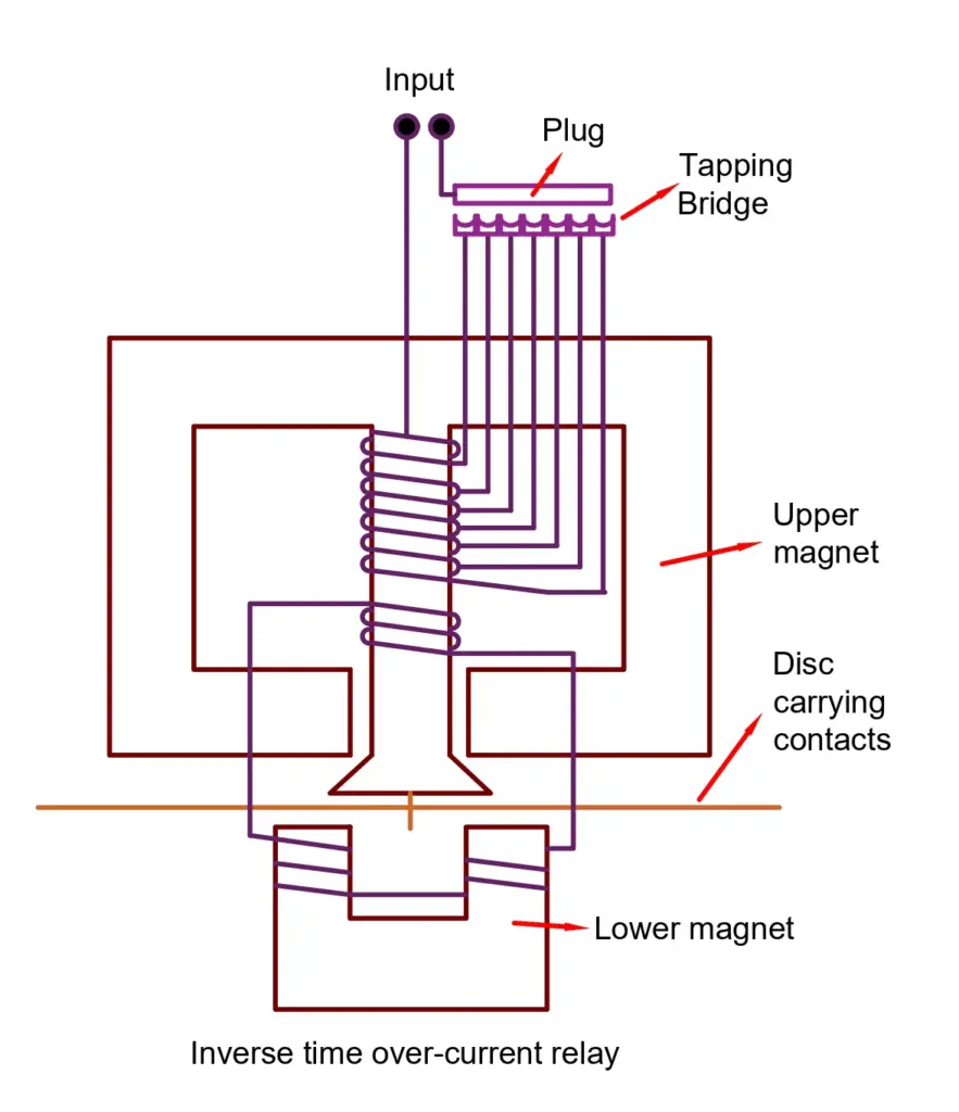
The induction disc carries a contact point. During an overcurrent situation, the disc rotates and closes the contacts of the circuit breaker. As a result, the circuit breaker immediately trips open the circuit and protects the system from the overcurrent fault.
If the delay time is set to zero, a definite-time relay works like that of an instantaneous relay.
The advantage of such relays is that they are reliable in places where speedy operation is sought to protect the system from surges. The inverse-time characteristic ensures protection at a higher speed when the current passing through the system is higher. It has a higher speed than that of a definite-time relay. These relays are present in both electromechanical types as well as microprocessor-based types.

There are the following types of inverse-time relays based on their time of operation.
- Normal Inverse time overcurrent relay
- Very Inverse time overcurrent relays
- Extremely inverse time overcurrent relay
- Long Time Inverse overcurrent relay
Inverse Definite Minimum Time (IDMT) Relays

Normal Inverse Relay
These relays have smaller operating times with a change in the current magnitude changes. These relays are used in utility systems.
Very Inverse Relay
The overcurrent relay with the very inverse characteristic curve is used in the feeder and on long transmission lines. The fault current falls at a rapid rate in the transmission line and therefore this relay curve is suitable for the protection of the transmission line.
Extremely Inverse Relay
The extremely inverse relay has an extremely large characteristic time as compared to IDMT and the very inverse relay. The relay trips faster when the pickup value exceeds the relay setting time. The relay is used for the protection of cables and transformers. This relay is used for protecting the cable, transformer, etc.
Long Time Inverse Overcurrent Relay
The relay has an extremely long operating time. These relays are used for those installations where there is a low risk of faults because these relays are not as sensitive as other types of overcurrent relays. It can take up to 60 seconds for clearing the fault.
A purely inverse-time relay is an ideal relay where the speed of operation increases commensurate with the amount of the overcurrent. In a practical scenario, however, an inverse-time relay has its own limitations.
As the current input to the system rises, the current transformer output rises causing the induction disc to rotate at a rapid speed and cause the circuit to break. But if the fault current is severely high, the core of the current transformer saturates.
Thus, the current output from the secondary of the Current Transformer stops rising proportionally even though the primary current rises because further magnetization of the CT stops. As a result, the induction disc of the relay can’t operate at a higher speed than that at the point of saturation of the current transformer.
Hence, the speed of the induction disc at the point of saturation is known as its maximum speed of operation. This is the minimum possible time for the relay to operate and it can’t be reduced further hence the name “ minimum time ”. The relay from this point onwards operates like a definite-time relay irrespective of the amount of rise in the current.

Applications of Overcurrent Relays
The really is used for protection of the following equipment.
- Feeder line protection
- Transformer Protection
- Motor Protection
- Capacitor bank protection
- Transformer Faults and Transformer Protection Schemes
- ANSI Device Numbers
- Classification of Relays | Different Types of Relays
- Difference Between Relay and Circuit Breaker
- Thermal Overload Relay- Working Principle, Types
1 thought on “Overcurrent Relay- Working Principle, Types, and Applications”
very good website link for all electrical engineer
Leave a Comment Cancel reply
Save my name, email, and website in this browser for the next time I comment.
Protection Against Overcurrents in Electrical Distribution
Compact NSX Circuit Breaker Overcurrent Trip Units
Compact NSX circuit breaker trip units are designed to handle overcurrents (overload currents and short-circuit currents) and in certain cases, ground fault currents.
o Pickup adjustments are calculated relative to the downstream circuit to be protected.
o Time delay adjustments are calculated in relation to the protection management (coordination).
NOTE: The protection plan is based on coordination of the protections - and in particular on discrimination. This can be achieved by time delays (time-related discrimination) while complying with ammeter- and power-related discrimination rules.
There are two types of trip unit:
o Thermal-magnetic trip units for Compact NSX100-250 circuit breakers
o Micrologic electronic trip units for Compact NSX100-630 circuit breakers
Standard Settings for Overcurrent Protections
Standard IEC/EN 60947-2 states the trip characteristics at the circuit breaker limits.
The following table summarizes the recommendations of standard IEC/EN 60947-2 for the circuit breaker protection function:
The Neutral Conductor
The installation rules closely define the type of protection to be used having regard to:
o Potential overcurrents (overloads and short-circuits).
o Conductors to be protected.
o Simultaneous cutoff of all conductors including the neutral conductor (multi-pole breaking).
NOTE: All three of the phase conductors must be protected at all times. The neutral conductor (if it is distributed and identical to the phases in size, that is, full neutral) is normally protected by the phase protection.
Description of the Neutral Protection
The neutral must have specific protection if:
o It is reduced in size compared to the phases.
o Nonlinear loads generating third order harmonics and multiples thereof are installed.
It may be necessary to cut off the neutral for functional reasons (multiple source diagram) or safety reasons (working with power off).
To summarize, the neutral conductor can be:
o Non-distributed (3P).
o Distributed, not cut off and not protected (3P).
o Distributed, not cut off but protected (3P with ENCT option). Refer to DOCA0141EN , Compact NSX Micrologic 5/6/7 Electronic Trip Units - User Guide .
o Distributed, cut off and protected (4P).
Compact NSX trip units are suitable for all protection types.
DOCA0140EN-01
© 2020 Schneider Electric. All rights reserved.
Cable Sizing Application

Click here to register to use our cable sizing application
What Changed
So that we can focus all our efforts on our new application, we have retired our myElectrical.com cable sizing calculator. We recommend you now use our main cable sizing application over at myCableEngineering.com .
myCableEngineering.com
- LV and MV cables up to 33 kV with current capacity in accordance with BS 7671, ERA 69-30 and IEC 60502.
- Positive and zero sequence impedance to IEC 60609. Voltage drop in accordance with CENELEC CLC/TR 50480.
- Project management and team collaboration, with clear easy to read calculations and reports.
Our software is the only cloud-based solution and has been built from the ground up to be fully responsive - meaning you can access your cables from anywhere and on any device, desktop, tablet or smartphone.
IDMT Tripping Time Calculator
Relay tripping time calculation according to IEC 60255 and IEEE.
Relay Details
Idmt tripping time calculation.
Tip: registered users can save calculations.
This morning I was explaining how differential protection works to a junior engineer. To give him something to read I opened up the NPAG (Network Protection...
A frequent problem in fault calculations is the obtaining of equipment parameters. While it is always preferable to use the actual parameters of the equipment...
GE's latest thinking on product manufacturing is he Shingijutsu philosophy or Lean production system. They have started applying this at the Louisville...
Low voltage (LV) switchrooms are common across all industries and one of the more common spatial requirements which need to be designed into a project...
ABB has produced a range of technical guides that offer concise explanations of the major technologies and technical issues in low voltage AC drives. ...
Following on from my post on railway electrification voltages, I thought an introduction to traction substations would be a good idea. Traction substations...
This is the first of two posts on the resistance of conductors. In the next post I will look at the ac resistance, including skin effect and we deal with...
In an earlier note on the site [Photovoltaic (PV) - Electrical Calculations], the theory of solar (PV) cell calculations was introduced. In particular...
The widely used United Sates standard ANSI/IEEE C37.2 'Electrical Power System Device Function Numbers, Acronyms, and Contact Designations' deals with...
The IEC publishes a series of documents and rules governing the preparation of documents, drawings and the referencing of equipment. Depending on country...
- Terms Of Use
- Privacy Statement
You are using an outdated browser. Please upgrade your browser to improve your experience.
Overcurrent Protection of ship electrical system
The general term “overcurrent” applies to a relatively small increase over the full load current ( FLC ) rating (e.g. due to mechanical overloading of a motor) rather than the massive current increase caused by a short-circuit fault.
Generally, an overcurrent , supplied from a CT, is detected by a relay with an appropriate time-delay to match the protected circuit.
Short-circuit faults in LV distribution circuits are mainly detected and cleared almost instantaneously bf fuses, MCCBs or MCBs.
Main supply feeders are usually protected against short-circuits by circuit breakers with instantaneous magnetic trip action.
Overcurrent relay types on ship:
Magnetic Thermal Electronic
All relay types have an inverse current- time characteristic called OCIT (over- current inverse time), i.e. the bigger the current the faster it will operate.
A magnetic relay , directly converts the current into an electromagnetic force to operate a trip switch.
An electronic overcurrent relay usually converts the measured current into a proportional voltage. This is then compared with a set voltage level within the unit which may be digital or analogue.
In analogue unit the time delay is obtained by the time taken to charge up a capacitor.
This type of relay has separate adjustments for overcurrent and time settings together with an instantaneous trip.
Both the magnetic and electronic relays can be designed to give an almost instantaneous trip (typically less than 0.05 seconds or 50 ms) to clear a short- circuit fault.
Thermal relays are commonly fitted in moulded case circuit breakers (MCCBs) and in miniature circuit-breakers (MCBs) to give a “long time” thermal overcurrent trip in addition to a magnetic action for an instantaneous trip with a short-circuit fault.
Overcurrent protection relays in large power circuits are generally driven by current transformers(CTs).
All overcurrent relays can be tested by injecting calibrated test currents into them to check their current trip levels and time delay settings.

Shop for mariners

© The Electro Technical Officer (ETO) | Disclaimer | Terms of Use | Privacy Policy | FAQ
Privacy Overview
Necessary cookies are absolutely essential for the website to function properly. This category only includes cookies that ensures basic functionalities and security features of the website. These cookies do not store any personal information.
Any cookies that may not be particularly necessary for the website to function and is used specifically to collect user personal data via analytics, ads, other embedded contents are termed as non-necessary cookies. It is mandatory to procure user consent prior to running these cookies on your website.

Democrats fret about the political fallout from the Trump rally shooting
M ILWAUKEE — In the hours after a would-be assassin fired a bullet through former President Donald Trump’s ear, Panfilo DiCenzo, a 40-year-old Democratic voter from Pittsburgh, drew a simple conclusion about the political effect of the attack: “It definitely is good for Trump.”
DiCenzo reasoned that undecided voters may “be more likely to vote for him out of sympathy” and that “especially with the upheaval in the Democratic Party, you know, more and more people I think are a little bit confused as to who to vote for.”
Follow live coverage here.
At a time when President Joe Biden has been struggling to shore up support with fellow Democrats following a miserable June debate performance and shaky cleanup effort, some professional Democratic political operatives said Saturday’s shooting will end up sealing the incumbent’s electoral fate.
“We’re so beyond f---ed,” one longtime Democratic insider said, noting that the image of Trump thrusting his fist in the air, with blood dramatically smeared across his face, will be indelible.
“The presidential contest ended last night,” said a veteran Democratic consultant, who spoke on the condition of anonymity to give a candid assessment of his own party’s standing less than four months before the election.
“Now it’s time to focus on keeping the Senate and trying to pick up the House,” he said. “The only positive thing to come out of last night for Democrats is we are no longer talking about Joe Biden’s age today.”
A Biden campaign spokesperson pointed to the president's Monday interview with NBC Nightly News host Lester Holt, along with his primetime speech scheduled for Sunday night, saying he would give "a forceful and needed address to update the nation on the horrifying attack on Donald Trump and the need for every American to come together to not just condemn, but put to an end political violence in this country once and for all."
"Following the president’s interview Monday evening, both the DNC and the campaign will continue drawing the contrast between our positive vision for the future and Trump and Republicans’ backwards-looking agenda over the course of the week," the campaign official said.
But in nearly a dozen interviews with Democratic strategists, operatives, aides and voters, there was a clear divide between Democrats who believe the attempt to kill Trump will end up helping him and those who say it won’t change much. Few suggested that it would improve Biden’s chances.
Cornell Belcher, a pollster who worked for former President Barack Obama, said that neither the shooting nor the debate would ultimately restructure a race that has been close all along. In particular, he said, there would be no dramatic shift among swing voters whose preferences will be important in the states that determine the election.
“Does that moderate, suburban, college-educated mom who is worried about how to pay for college for her daughter and whether her daughter will have as many rights in her life as she has had in hers — does the shooting make her go, ‘Oh, my God! I’m going to vote for Trump!’ No,” he said.
One Democratic strategist who has worked on multiple presidential campaigns and on Capitol Hill said that the physical targeting of Trump robs Biden of his main argument against the former president. Biden, the strategist pointed out, has tried to convince voters that Trump is so extreme that he presents a threat to democracy.
“That message is dead,” the strategist said, after a gunman tried to kill the presumptive nominee of one of the two major parties. The bullet that struck Trump “probably saved Biden’s nomination” by freezing Democratic calls for him to step aside and “doomed his re-election.”
Adam Green, co-founder of the Progressive Change Campaign Committee, echoed that sentiment.
“I’m very concerned that the net effect of the Republican convention will be neutralizing the core democracy critique of Trump — a felon who fomented a violent insurrection, tried to block the peaceful transfer of power, and said the Constitution may need to be terminated,” he said.
“There is a race to define the democracy critique of Trump as legitimate,” Green added, “and we all need to make clear now that protecting democracy is the exact opposite of political violence.”
Most of those who questioned whether Trump would ultimately benefit politically from the attempt on his life — and his reaction to it — framed their own views as counterintuitive or at least at odds with the majority of Democrats in their circles.
One Biden ally said the close call for Trump would further solidify his base without bringing him new voters. Biden has responded to chaotic times by demonstrating steady leadership, the ally said, adding the prediction that Biden would lift a pause on his campaigning during the Republican convention this week.
A second veteran Democratic strategist said that his first-blush impression was that the shooting would help Trump but that he had reconsidered.
“Politically, the notion that this is going to help Trump is flawed. I think this reminds them that he is a chaos maker,” the strategist said. “This is when we need someone to bring us together.”
He added that he believes Republicans run a political risk if the speakers at the convention echo Trump’s past calls for retribution instead of tamping down their rhetoric.
A Democratic operative with experience as a senior presidential campaign adviser predicted there would be a “slight immediate bump” for Trump with certain demographic groups. “But fundamentally, I think the race stays where it has always been. And we’ve got many moons still to go, as crazy as that seems.”
The operative said it is “so bizarre” that “many people on my side are firmly in the camp of [Biden] can’t win,” describing that view as a “vibes analysis” without a “rational basis.”
Public polls have shown the election is closely contested in enough swing states that either candidate could assemble an Electoral College majority.
A Trump spokesperson did not reply to NBC News’ request for comment on whether the campaign views the attempted assassination as an asset on the campaign trail. But Trump used the already-iconic photo of him raising his fist in the air, while surrounded by his protective detail, in a fundraising appeal Sunday. A full-color American flag appears in the background of a black-and-white version of the photo used to pitch for donations. The words “NEVER SURRENDER” are emblazoned across the top of the image.
For one veteran of Democratic congressional campaigns, that picture says it all.
“The clear effect of this assassination attempt is that it officially thrust Donald Trump out of politics and into martyrdom,” this person said. “They’re framing this as an attack on MAGA and not on Trump — even more powerful. This is literally biblical stuff we’re talking about.”
Democrats will “never be able to compete with that level of enthusiasm among base voters,” the person added. “So yeah, we’re even more f---ed with Biden. ... And relying on Trump to be a galvanizing, unifying enemy won’t work as well.”
This article was originally published on NBCNews.com

- Cast & crew
- User reviews
Fly Me to the Moon

Marketing maven Kelly Jones wreaks havoc on launch director Cole Davis's already difficult task. When the White House deems the mission too important to fail, the countdown truly begins. Marketing maven Kelly Jones wreaks havoc on launch director Cole Davis's already difficult task. When the White House deems the mission too important to fail, the countdown truly begins. Marketing maven Kelly Jones wreaks havoc on launch director Cole Davis's already difficult task. When the White House deems the mission too important to fail, the countdown truly begins.
- Greg Berlanti
- Keenan Flynn
- Bill Kirstein
- Rose Gilroy
- Scarlett Johansson
- Channing Tatum
- Woody Harrelson
- 63 User reviews
- 105 Critic reviews
- 52 Metascore
- 2 nominations

- Kelly Jones

- Henry Smalls

- Lance Vespertine

- Ruby Martin

- Buzz Aldrin

- Neil Armstrong

- Michael Collins

- Senator Hopp

- Senator Vanning

- Jolene Vanning

- Senator Cook

- Wolfie's Joe
- All cast & crew
- Production, box office & more at IMDbPro
Burning Qs for Scarlett and Channing
More like this.

Did you know
- Trivia A launch did occur at Cape Canaveral during production. The second unit was able to record the launch with their 4K cameras.
- Goofs During the party a record stylus is shown and lowered to a record, the bee gees song immediately starts playing from the beginning, but the stylus is shown to be lowered on the end of a track.
Moe Berkus : Pilots fight gravity. It's their nature.
- Soundtracks Hold On I'm Coming performed by Chuck Jackson & Maxine Brown
User reviews 63
- Jul 11, 2024
- July 12, 2024 (United States)
- United States
- United Kingdom
- Official Site
- Project Artemis
- Cape Canaveral, Florida, USA (Shooting at Kennedy Space Center March 2023)
- Apple Studios
- These Pictures
- See more company credits at IMDbPro
- Jul 14, 2024
- $18,402,176
Technical specs
- Runtime 2 hours 12 minutes
Related news
Contribute to this page.

- See more gaps
- Learn more about contributing
More to explore
Recently viewed.
EXCLUSIVE: Watch NBC News anchor Lester Holt's full interview with Biden
After Trump assassination attempt, a reckoning over American political rhetoric
BUTLER, Pa. — A day after the shocking assassination attempt on former President Donald Trump at a campaign rally in Pennsylvania, the nation is left wondering whether the political polarization that has gripped the country has grown too severe.
Condolences and calls to turn down the rhetorical heat poured in from across the country and the world as leaders of all political stripes expressed shock and horror at the first shooting of a U.S. president since Ronald Reagan was nearly killed more than 40 years ago while leaving a hotel in Washington.
In a prime-time Oval Office address Sunday night, President Joe Biden urged Americans to "lower the temperature in our politics."
"While we may disagree, we are not enemies," Biden said during his approximately six minutes of remarks condemning the attempted assassination on his predecessor. "We're neighbors, we're friends, coworkers, citizens, and most importantly, we are fellow Americans. We must stand together."
The president said that he was “grateful” that Trump was doing well, and he expressed condolences for the rally attendee who was killed.
"A former president was shot, an American citizen killed while simply exercising his freedom to support the candidate of his choosing,” Biden said. “We cannot, we must not go down this road in America.”
“Disagreement is inevitable in American democracy,” Biden added later, emphasizing that politics should never turn into a “killing field.”
The president said that Americans should resolve disagreements at the ballot box, "not with bullets." He urged unity, adding, "We can do this."
“We’re all Americans, and we have to treat one another with dignity and respect,” House Speaker Mike Johnson said in an interview Sunday on NBC News’ “Weekend Today.” He went on to echo the blame that Trump allies are placing on Biden, who used the word “ bull’s-eye ” on a campaign call with donors last week.
“I mean, I know that he didn’t mean what is being implied there,” Johnson said Sunday about Biden’s comments, but added, “That kind of language on either side should be called out.”
Violence tends to beget more violence and experts fear the shooting will inflame, rather than calm, tensions heading into a presidential campaign whose stakes are seen as existential by both sides.
“This is a very dark moment in our history, and unfortunately this is very unlikely to be the end of political violence this election season,” said Jacob Ware, a research fellow at the Council on Foreign Relations who studies domestic and international terrorism. “A whole range of scenarios, from low-level vigilante violence to higher-profile assassination attempts, will likely characterize the next several months.”
Once violence becomes seen as a legitimate avenue to settle political scores, "it’s difficult to know how to reverse that development," Ware added.
Violent rhetoric has become a more familiar part of political campaigns in recent years, as has sometimes violent clashes between protesters, counter-protesters and police. But assassinations have not been seen in American politics for decades.
Trump, who was hit in the ear by a bullet, was released from the hospital Saturday night, while two spectators who were seriously injured remain hospitalized. Another spectator was killed .
The two injured rally attendees are in stable condition, according to the Pennsylvania State Police.
“In this moment, it is more important than ever that we stand United, and show our True Character as Americans, remaining Strong and Determined, and not allowing Evil to Win,” Trump wrote on the website Truth Social on Sunday morning.
Biden also urged unity during his Oval Office address and earlier remarks at the White House on Sunday.
"Here in America, while unity is the most elusive of all goals right now, nothing is more important for us now than standing together," Biden said Sunday night.
How the shooting unfolded
Witnesses at the rally described a chaotic scene in the moments after the shooting.
In the front row of the rally, attendees heard a series of pops and saw Secret Service agents jump on the stage. One, who identified herself as Erin, told NBC News that she saw blood on Trump’s ear. She did not fear for her own safety, she said. “We were only concerned about him,” she said, referring to Trump.
Investigators have yet to say how the shooter, identified by the FBI as 20-year-old Thomas Matthew Crooks of Bethel Park, Pennsylvania, was able to get close enough to shoot at Trump.
Police have also not suggested a motive for Crooks, who was killed by police moments after he opened fire. Voter registration records show that Crooks was a registered Republican, but so far, authorities have offered no political motivations for the shooting.
The FBI is investigating the attack as potential domestic terrorism and an assassination attempt, according to a statement, which noted that the investigation indicates that the shooter acted alone.
The FBI said that the suspect was "not known to the FBI prior to this incident." FBI Pittsburgh Special Agent in Charge Kevin Rojek said earlier that there were no indications that the suspect had mental health issues.
The weapon allegedly used by Crooks was found at the crime scene, Rojek said. The firearm was "purchased legally," according to the FBI.
The FBI said the bureau found "suspicious devices" in the suspect's home and vehicle. The devices were "rendered safe by bomb technicians and are being evaluated at the FBI Laboratory."
The FBI also obtained the shooter's phone for examination, according to the statement.
Some prominent Republicans pointed to Biden's rhetoric at the motivation before the shooter was even identified. Biden's allies pushed back, pointing to the number of times the sitting president has condemned political violence.
Experts cautioned to not jump to partisan conclusions about Crooks’ motive, noting that shooters often struggle with mental illness, which makes their motives unintelligible to the rest of the world. Reagan’s would-be assassin, John Hinckley, has said he was trying to impress actress Jodie Foster after being infatuated with her performance in the film Taxi Driver. The man who shot former Rep. Gabby Giffords, Jared Loughner, was diagnosed with paranoid schizophrenia and his writings espoused what one scholar called a “ toxic jumble of left- and right-wing conspiracy theories, his sources ranging from Marx to Hitler to heavy metal.”
Anthony Guglielmi, chief of communications for the U.S. Secret Service, pushed back on assertions that Trump’s campaign had requested but been denied additional resources.
“There’s an untrue assertion that a member of the former President’s team requested additional security resources & that those were rebuffed,” he posted on X.
“This is absolutely false. In fact, we added protective resources & technology & capabilities as part of the increased campaign travel tempo.”
The chairman of the House Homeland Security Committee demanded answers from the Secret Service and their bosses at the Department of Homeland Security in a letter Sunday.
“The seriousness of this security failure and chilling moment in our nation’s history cannot be understated," Rep. Mark E. Green, R-Tenn., wrote in the letter. "Had the bullet’s trajectory been slightly different, the assassination attempt on President Trump might have succeeded."
A bipartisan group of House lawmakers quickly introduced a measure to enhance Secret Service protection for Trump and Biden, as well as grant it to independent presidential candidate Robert F. Kennedy, Jr., who has accused Biden of denying him official protection for political reasons. (The White House denied that, noting the Department of Homeland Security along with congressional leaders are responsible for such decisions.)
“Last night’s attempted assassination of former President Trump was a dark moment in our nation’s history. As reports continue to emerge, it’s clear that more protection is needed for all major candidates for president," New York Reps. Mike Lawler, a Republican, and Ritchie Torres, a Democrat, said in a joint statement.
House Homeland Security Committee Chair Mark Green, R-Tenn., held a call on Sunday with Secret Service Director Kimberly Cheatle, according to a committee spokesperson.
Campaign season thrown into turmoil
The assassination attempt has upended a presidential campaign that was already in the grips of tumult, as fellow Democrats called on Biden to step aside after a debate performance last month left many wondering about the 81-year-old's mental and physical fitness.
The Republican National Convention is set to begin Monday to formally nominate Trump.
Audrey Gibson-Cicchino, the Secret Service’s 2024 RNC coordinator, said during a Sunday press briefing that there are no changes to operational security plans for the convention.
Officials expressed confidence during the briefing that they are prepared for the convention, reiterating that it was already designated as a National Special Security Event, the highest federal security designation.
Still, Trump campaign officials advised staff to avoid the campaign's offices in Florida and Washington, D.C., until their security can be assessed.
“It’s sick. It’s sick. It’s one of the reasons we have to unite this country,” Biden said in remarks late Saturday night, before he was able to speak with Trump. “We cannot condone this.”
First lady Jill Biden spoke over the phone with former first lady Melania Trump on Sunday, according to a White House official.
Former presidents Barack Obama, George W. Bush and Bill Clinton released similar statements condemning the attack and calling for unity, while foreign allies like new U.K. Prime Minister Keir Starmer said, “Political violence in any form has no place in our societies."
Democratic National Committee Chair Jaime Harrison had a "brief call" with Republican National Committee Chair Michael Whatley on Saturday, according to a DNC spokesperson.
During the call, Harrison offered "his thoughts and condolences" and emphasized "the Democratic Party’s continued opposition to any and all forms of political violence," according to the spokesperson.
Senate Minority Leader Mitch McConnell, R-Ky., told attendees at an RNC event that "we are not going to let this kind of hatred redefine this country," according to a spokesperson.
David Brown, a Trump supporter from Pittsburgh, told NBC News on Sunday that like many Americans, he feels political animosity has gotten out of hand.
"We really need to take a deep breath," Brown said. "I’m friends with a lot of Democrats, and they’re great people, but I think we need to realize that we’re demonizing each other too much... We need to look past that white noise, so to speak."
On the other side of the aisle, Panfilo DiCenzo, a 40-year-old reluctant Democratic voter, saw the shooting as "a symptom of our current state, politically, socially."
He pointed to political division and cultural and economic upheaval, saying it created "a lot of frustrated individuals.”
Minyvonne Burke is a senior breaking news reporter for NBC News.
Alex Seitz-Wald is a senior political reporter for NBC News.
Megan Lebowitz is a politics reporter for NBC News.
Politics latest: Voters ousted Conservative Party over 'incompetence', survey finds
A massive survey has revealed why voters decided to turn away from the Conservatives at the election. Foreign Secretary David Lammy has held talks with the president of Israel. Meanwhile, Sir Keir Starmer has announced he wants to break down the barriers of opportunity in football.
Monday 15 July 2024 22:57, UK
- General Election 2024
Please use Chrome browser for a more accessible video player
- A survey has found voters were unhappy at Conservative 'incompetence'
- David Lammy has called for an immediate ceasefire in Gaza.
- Government announces plan to break down 'barriers of opportunity' in football after Euros campaigns
- Labour will be "far more Gareth Southgate and far less Michael Gove"
- Poison spreading into politics on both sides of the Atlantic - minister
- Labour plans for 35 new bills in King's Speech
- PJAS: Keir's coming home
- Jon Craig: Assassination attempt on Trump is a wake-up call for UK MPs
- Live reporting by Tim Baker and Jennifer Scott
We are handing over to the US now where the Republicans are meeting to confirm Donald Trump as the candidate for the presidential election, just days after an assassination attempt on his life.
Follow all the news from the massive convention in Milwaukee with our colleagues by clicking here .
We will be back tomorrow to bring you all the latest from Westminster. For now though, have a good evening!
Now to the SNP's Stephen Gethins, who is calling on the new government to scrap the two-child benefit cap.
The measure was brought in by the Conservatives in 2017, preventing parents claiming Universal Credit or child tax credits for a third child, except in very limited circumstances.
It means families cannot claim about £3,200 a year per extra child, the Resolution Foundation has said.
But scrapping it would be estimated to cost £1.7bn. So how do you pay for it?
"You can increase borrowing," suggests Mr Gethins. "You could also, like Scotland, have a slightly more progressive taxation system where those with lower wages in Scotland, pay less tax bills and those with higher wages pay more tax.
"We're not just talking about a Westminster game here. We're talking about the way in which, you know, kids that will go hungry, how do you heat your house going into the winter time?"
He also points to what the government has already spent money on.
Mr Gethins says: "Let's put it this into perspective, you know, leaving the EU has already cost us £140bn. A replacement for Trident will cost £200bn. And you're talking about £1.5bn in terms of child poverty.
"Politics is about choices. It's about priorities. And we think child poverty should be a priority."
Labour MP Dawn Butler says she faced intimidation during the election, and there was "definitely more aggression in the air".
But she tells Sophy there has been "been a build up of sort of violent talk and rhetoric" for years, pointing back to the days of Brexit.
Ms Butler said in the last campaign there "seemed to be a strategy to film and follow, especially female MPs", and to abuse them.
"I had somebody following me and being very aggressive and shouting and recording," she adds. "But that's with the police so I don't want to talk too much about that.
"But just today, we had to report somebody to the police who was trying to, you know, advocate violence against me, and so I think social media has a huge role to play with that."
Former special adviser James Starkie agreed with the social media issue, as it is "dehumanising".
"When I walk into Conservative Party conference this year... there'll be someone screaming in my face 'you're scum' as I walk in," he said.
"Now, if I walk down the street and someone started screaming in my face... and there was a police officer, that person would be arrested. But they won't be at conference.
"So there is a kind of weird acceptance that you're allowed to treat politicians in a way that actually we wouldn't expect say, a chief executive to be treated."
Lord Walney has written to the home secretary calling for an inquiry into the intimidation of MPs after what Sophy Ridge calls one of the "ugliest" election campaigns we have seen in the UK - and, of course, after an assassination attempt on former US president Donald Trump.
The peer tells Sophy the incident this weekend was "a shocking reminder of the vulnerability that everyone who puts themselves in the front line to serve ultimately faces".
He says politicians are "blessed in to be here in the UK where there is not the same gun culture" as across the Atlantic.
But he says the fact the shooter came within "less than an inch" of killing Mr Trump showed all politicians face "some level of threat".
Lord Walney adds: "There is no way of reducing that to zero. MPs who go put themselves forward to serve their communities, none of them will accept being sealed away behind bulletproof glass. They they are there to be part of their communities to listen."
He praises Home Secretary Yvette Cooper, who has announced she is chairing a taskforce to look into the "alarming" intimidation of candidates.
But he said there should be "a much needed review of security around Whitehall", and different elements, including police and government, need to work together to address the issue.
It's time for the Politics Hub with Sophy Ridge, and tonight the guests include the SNP's Stephen Gethings and Lord Walney, the government's adviser on political violence.
Our panel is made up of returning Labour MP Dawn Butler and former chief of staff to Priti Patel, James Starkie.
Make sure you tune in on the video stream above, and we will bring you updates too.
Yvette Cooper has announced she will chair a meeting of the government's "Defending Democracy" taskforce next week.
The home secretary this was following an “alarming rise” in harassment towards political candidates and campaigners.
In a statement this afternoon, Cooper said she would be speaking to MPs about their experience of the election campaign.
"Political violence, intimidation and harassment have no place in our democracy," she said.
"In our democracy we must be able to passionately debate and disagree on issues without ever resorting to intimidating tactics designed to silence voices, suppress votes or prevent free and full participation in our democratic processes.
Cooper added: “The disgraceful scenes we saw in some areas during this election campaign must not be repeated."
By Tomos Evans , Wales reporter
The Welsh first minister's former leadership rival has refused to say he has confidence in his leader.
Wales's economy secretary Jeremy Miles failed to back Vaughan Gething four times.
In an interview with ITV Wales on Monday, Mr Miles said it wasn't "helpful to give a running commentary".
But Mr Miles, who lost out to Mr Gething in March, acknowledged it had been "a difficult few weeks".
Last week, former government minister Hannah Blythyn, who was sacked by the first minister for allegedly leaking to the media, spoke out.
She denied having leaked a series of iMessages, in which Mr Gething appeared to say he would be "deleting" messages which could be "captured in an FOI".
News website Nation.Cymru, which first broke the story, last week confirmed Ms Blythyn was not its source for the story.
A motion has been tabled in the Senedd for Wednesday, calling on the government to publish the evidence upon which Ms Blythyn was sacked.
The Office for National Statistics (ONS) has released its latest migration stats for the year to mid-2023.
It has found that, for England and Wales, the population grew by the greatest amount since 1948 - when soldiers were returning from the Second World War and birth rates were very high.
The net increase of people in the two nations was 610,000, to a total of 60.9 million.
This was mostly down to 1,084,000 people immigrating into England and Wales from outside the UK - while 462,000 left.
In terms of births and deaths, only 400 more people were born in the UK than died in the 12-month period - the lowest figure since 1978.
Some 598,000 people died in the year to mid-2023, while 598,400 were born.
Deaths were up 24,000 compared to the previous 12 months, while births were down 21,900.
Head of population estimates for the ONS, Neil Park, said: "High levels of international migration seen in recent years are the main driver of population growth.
"But the year to mid-2023 also saw an increased number of deaths, as well as the lowest number of births since 2002.
"In fact, in the most recent year, births outnumbered deaths by just 400, the lowest reported figure for natural change since the late 1970s. And, interestingly, there were more deaths than births in every region, with the exception of London and the West Midlands."
By Faye Brown , political reporter
Rishi Sunak has been urged to stay on as Conservative leader until November amid divisions within the party over how long the contest to replace him should take.
Shadow foreign secretary Andrew Mitchell said the former prime minister's instinct "is almost certainly to go" but more time was needed for potential successors to make their case.
The view is at odds with other senior figures who fear a protracted contest would leave a vacuum for Labour and Reform UK to capitalise on.
Mr Mitchell told Times Radio on Monday: "An interim leader is not, in my view, the best option.
"The best option is to seek to persuade Rishi to remain. It's not an enormously long time in the scope of things. It's probably 'til mid to end November."
He added: "I think his instinct is almost certainly to go. I hope that he won't."
Read the full story here:
Here's a little bit more from the massive More in Common analysis that came out earlier today.
The work relied on surveys and interviews with more than 10,000 people.
The group found that - by a huge margin - voters of every persuasion attributed the Conservative Party's loss to incompetence, rather than being too right wing or left.
The report said that Mr Sunak's U-turn on net zero went down badly - as did axing the northern leg of HS2.
This compounded with the former PM failing to stop the boats or cut NHS waiting lists, as he pledged to do.
Be the first to get Breaking News
Install the Sky News app for free

IMAGES
VIDEO
COMMENTS
Time Overcurrent Relay Curves. Time overcurrent relays exhibit different "curves" relating trip time to multiples of pickup current. All 51 relays are inverse in that the amount of time to trip varies inversely with overcurrent magnitude: the greater the sensed current, the less time to trip. However, the function of trip time versus ...
As mentioned in parameters, a Time Dial Multiplier (TDM) is sometimes specified by the relay manufacturer instead of a Time Dial (TD). See conversion here. The Inverse Time Over Current (TOC/IDMT) relay trip time calculator calculates the protection trip time according to IEC 60255 and IEEE C37.112-1996 protection curves.
The characteristics of overcurrent relays are based on operating times typically governed by a time vs. current curve. There are three main types of overcurrent relay: (1) Instantaneous, (2) Time-Dependent (Definite time or inverse), and (3) Mixed (Definite time and Inverse). 1. Instantaneous relays have operating times usually less than 3 cycles.
The thermal element acts as protection from overloading while the magnetic element is for protection from faults. This allows slow operation on overload and fast on fault. A typical time-current curve is shown in figure 6. Thermal Magnetic trip devices may be fixed or adjustable based on the ampere rating. Figure 6.
Radial electrical system with time discrimination. Overcurrent relay protection is given at B, C, D and E, that is, at the infeed position of each part of the electrical power system. Each relay protection device comprises a definite-time delay overcurrent protection relay in which the trip of the current sensitive element starts the time delay ...
1. Definite (instantaneous)-current protection. This relay is referred as definite (instantaneous) overcurrent relay. The relay operates as soon as the current gets higher than a preset value. There is no intentional time delay set. There is always an inherent time delay of the order of a few milliseconds.
Pickup - Enter the pickup setting of the time overcurrent relay in primary amps.. Time Dial - Enter the Time Dial setting of the time overcurrent relay. This should be 0.50 - 15.00 for U.S. curves and 0.05 - 1.00 for IEC curves. Curve - Select the Curve setting of the time overcurrent relay.. Fault Current - Enter the Fault Current for which the operate time should be calculated.
50/51 and 50/51N relays. Overcurrent relays are the most commonly-used protective relay type. Time-overcurrent relays are available with various timing characteristics to coordinate with other protective devices and to protect specific equipment. Instantaneous overcurrent relays have no inherent time delay and are used for fast short-circuit ...
A definite time overcurrent relay can be adjusted to issue a trip output at an exact amount of time after it picks up. Thus, it has a time setting adjustment and pickup adjustment. ... Inverse Definite Minimum Time Over Current Relay or IDMT O/C Relay. In an overcurrent relay, achieving perfect inverse time characteristics is challenging.
The standard IDMT overcurrent characteristics are expressed as a mathematical formula according to the IEC 60255-3/BS142 and IEEE C37.112-1996 standards and are often the basis of the electromechanical time current curves. ... follow the relay curve characteristic up to 4000 amperes (100 x 2 x 20). Above that threshold, the time to trip will ...
Types of Overcurrent Relay - Definite Time, Inverse Time & IDMT Relays. A protective relay that operates when the current flowing in the circuit reaches a predetermined value is called Overcurrent Relay. The predetermined value of the current at which the relay starts operating by initiating a trip signal is known as its pick-up value.
Here, as defined in IEC 60255, the IDMT Tripping Time T (s) is multiplication of Time Setting Multiplier (TSM) by the k curve constant divided by the division of fault current I (F) in Amps to relay Current setting Is (A) in amps power of curve constant α minus 1. Hence the formula can be written as, T (s) = TSM * (k / ( (I (F) /Is (A) ) α ...
Inverse definite minimum time (IDMT) relays serve the purpose of interrupting the fault currents while ensuring safety and minimising damage to power system equipment. To achieve this, relays are supposed to trip in a short time therefore it is of great importance to know the tripping time. For protection discrimination studies you can use our ...
Overcurrent refers to an electrical condition in a circuit where the current flowing through the conductors exceeds the rated or designed current-carrying capacity of the components, such as wires, fuses, circuit breakers, and other protective devices. Overcurrent can occur due to various factors and can have different consequences, including ...
This calculator uses formuals found in the IEC Standard 60255 and the IEEE C37.112 standard to calculate the tripping times. The formula used in the IEC 60255 calculation is; t (i)=\left ( \frac {K} { { (\frac {I} {I_s}})^ {p}-1} \right) *TMS. Where; I is the fault current in Amps, TMS is the Time Multiplier setting on the protection relay, Is ...
A definite time overcurrent relay comes into action after an intentional time delay. Unlike the instantaneous overcurrent relay which causes the circuit to trip-open immediately in case of an overcurrent situation, a definite-time overcurrent relay allows the overcurrent or the overload to sustain for a certain period of threshold time.
Protection function. Setting recommendations. Long-time protection. Long-time protection of the inverse time type (with I 2 t constant):. o No trip for a current below 105% of Ir. o Trip in less than two hours for a current equal to:. o 120% of Ir for an electronic trip unit. o 130% of Ir for a thermal-magnetic trip unit. For a higher fault current, the trip time is inversely proportional to ...
The current setting of overcurrent relay is generally ranged from 50 % to 200 %, in steps of 25 %. For earth fault relay it is from 10% to 70% in steps of 10%. ... That means the moving parts of the relay take total 3 seconds to travel 100 % traveling distance. As the time setting multiplier is 0.1 here, actually the moving parts of the relay ...
The time for which the OL should pause before reacting will be different for various motors and applications is called the motor trip class. The most common trip classes are 5, 10, 20, and 30, which refer to the number of seconds for which the OL will allow this 600% current in-rush. Applications for each of these trip classes can be classified ...
Cable Sizing Software - select, size and manage your power cables using myCableEngineering. All your cables, for all your projects. LV and MV cables up to 33 kV with current capacity in accordance with BS 7671, ERA 69-30 and IEC 60502. Positive and zero sequence impedance to IEC 60609. Voltage drop in accordance with CENELEC CLC/TR 50480.
Overload trip classes appear most often as class 10, 20, or 30. These numbers relate to the number of seconds that the overload will maintain contact if an excessive inrush current is experienced. If the current is 6x the full-load amps of the overcurrent relay, the class 10 device will trip after 10 seconds, class 20 after 20 seconds, and ...
The thermal magnetic trip unit consists of two parts: The thermal trip unit - Made up of a bimetallic thermal device which actuates the opening of a circuit breaker with a delay depending on the overcurrent value; for overload protection.. The magnetic trip unit - Made up of an electromagnetic device, with a fixed (fixed instantaneous trip) or adjustable (adjustable instantaneous trip ...
Overcurrent protection relays in large power circuits are generally driven by current transformers (CTs). All overcurrent relays can be tested by injecting calibrated test currents into them to check their current trip levels and time delay settings. TeSys LT47 Electronic Overcurrent Relay LT4706EA LT47-06EA Automatic 0.5…6 A 48 V AC/DC.
BUTLER, Pa. — Former President Donald Trump was injured in an assassination attempt Saturday when a gunman opened fire at his campaign rally, killing one spectator and bloodying Trump's ear.
The students visited Ocean Isle Beach on Sunday, July 14, during a break on the trip and decided to go swimming, officials said. ... He said school officials won't release her name at this time.
Travel activity is expected to heat up to record levels around the Independence Day holiday as consumers take advantage of cooler prices for airfares, gasoline and hotels. ... It said total customer deposits reached an all-time high of $8.3 billion during its fiscal second quarter and it expects capacity to grow 4.8% in 2024. Competitor Royal ...
M ILWAUKEE — In the hours after a would-be assassin fired a bullet through former President Donald Trump's ear, Panfilo DiCenzo, a 40-year-old Democratic voter from Pittsburgh, drew a simple ...
Fly Me to the Moon: Directed by Greg Berlanti. With Scarlett Johansson, Channing Tatum, Woody Harrelson, Ray Romano. Marketing maven Kelly Jones wreaks havoc on launch director Cole Davis's already difficult task. When the White House deems the mission too important to fail, the countdown truly begins.
In a prime-time Oval Office address Sunday night, President Joe Biden urged Americans to "lower the temperature in our politics." "While we may disagree, we are not enemies," Biden said during his ...
Well a separate piece of research - this time from More in Common and UCL - has shown what issues are the key tests for Labour. The surveyors asked more than 10,000 people for their opinions.